preparation
3-D Crystals
IV
REMARK : When the reader feels satisfied with our established theoretical foundation (done in previous documents) that allows (single, non-twinned) Crystals to be promorphologically assessed, he or she can skip all the following, and directly proceed with The Promorphology of Crystals.
Deriving the Complex Motif of Calcite (CaCO3)
Chemical bonding and Structure Control in Crystals
Before we're going to analyze the structure of Calcite crystals in order to find the Complex Motif (that lies at the base of the crystal's tectological structural aspect), something must be said with respect to chemical bonding and ionic radii, both controlling the internal structure of crystals.
In crystals we can encounter several distinct b o n d i n g t y p e s , namely covalent bonding, van der Waals bonding, hydrogen bonding and ionic bonding.
Covalent bonds controlling structure.
Covalent bonds are typically quite strong, so covalent crystals are hard and have high melting points. The strong d i r e c t i o n a l nature of covalent bonds requires that the atoms be placed in specific o r i e n t a t i o n s so that orbitals can overlap (See the first part of this website -- accessible via back to homepage -- The Chemical Bond (Non-classical Series)). This often prevents the atoms from acquiring a close-packed arrangement.
Molecular bonds controlling structure.
Molecular crystals consist of discrete molecules packed together in a systematic way. Each molecule in the structure is typically bonded internally with covalent bonds and lacks a residual charge or valence with which to bond with other atoms. The forces that hold the molecules to each other are limited to relatively weak van der Waals and hydrogen bonds. Molecular crystals are therefore quite soft. The geometry of the structure is controlled by the shape and charge distribution of the individual molecules and the pattern by which they can be systematically packed together. For example in Ice (H2O) hydrogen bonding holds water molecules in a hexagonal structure that is reflected in the hexagonal shape of snow flakes.
Ionic bonds controlling structure.
Ionic bonding involves the electrostatic force obtaining between positively charged ions and negatively charged ions (an ion is an electrically charged atom or atomic group).
Because ionic bonds are not directional, we can, as a first approximation, look to the manner in which cations (positively charged ions) and anions (negatively charged ions) bond together in purely geometrical terms, unencumbered by the complexities of aligning orbitals in the specific orientations required for covalent bonds. In doing so we can imagine a cation -- that is normally relatively small -- being in contact with several anions (that are normally larger). In what way (i.e. in what kind of arrangement) those anions group themselves around a cation is expressed by the c o o r d i n a t i o n p r i n c i p l e. The coordination principle states that how anions and cations pack together in a crystal structure depends on their relative sizes (radii). A cation's coordination number (CN) is the number of anions with which it is in contact. When the bonding is dominantly ionic, each cation will attract or coordinate with as many anions as it can pack around itself. The c o o r d i n a t i o n p o l y h e d r o n is the shape defined by anions coordinating with a cation. Twelve-fold coordination is the largest common coordination number. The coordination number is dependent on the r a d i u s r a t i o between cation and anion, where the radius ratio is the ratio of the radius of the cation and that of anion.
The most important coordination numbers are listed below.
As has been said, a certain coordination of anions around a cation defines a polyhedron, a c o o r d i n a t i o n p o l y h e d r o n. We find such a polyhedron when we interpret the centers of the anions (that are grouped around one central cation) as the corners of a polyhedron. The particular coordination is called after the coordination polyhedron that it involves. As has been promised, some important coordinations will be listed :
The Electrostatic Valence Principle
(NESSE, W., 2000, Introduction to Mineralogy, p. 62).
For an ionic bond, the b o n d i n g c a p a c i t y of an ion is proportional to its oxidation state (charge). The s t r e n g t h of the electrostatic valence bonds (EVB) reaching an ion is therefore equal to the charge of the ion divided by the number of oppositely charged ions with which it coordinates, i.e., the coordination number (CN) :
EVB = ion charge/CN
Although this relationship is straightforward, it leads to some interesting consequences.
UNIFORM BOND STRENGTH
First consider the case in which all ionic bonds have the same strength. We call this i s o d e s m i c. This will be the case for all ionic minerals and other ionic compounds with a single anion and single cation, as well as some minerals (and other compounds) with multiple cations and/or anions. If all the cation-anion bonds are the same strength, it is impossible for any bond to occupy more than half of the anion's charge because the smallest possible coordination number is two. Because the anion-cation bonds are all uniform, the anions tend to pack together in a highly symmetrical arrangement and the cations occupy polyhedra formed by the interstices among the anions. Some of the common structures are based on cubic or hexagonal closest packing of the anions. It should be no surprise that most of these substances are higly symmetrical and crystallize in the Isometric, Tetragonal, or Hexagonal Crystal Systems.
Substances with uniform bond strengths are conveniently classified as Oxides, Fluorides, Chlorides, etc., based on the identity of the anion.
NON-UNIFORM BOND STRENGTH
In some structures certain anion-cation bonds are stronger than others. The cations forming stronger bonds are small and possess a high charge, for example C4+, S6+, P 5+, and Si4+. Because these cations strongly bond to the anions (usually O2-) the result is the formation of CO32-, SO42-, PO43-, and SiO44- anionic groups that serve as structural elements in their crystal's structures.
Crystals with non-uniform bond strengths typically have lower symmetry than those in which bond strengths are uniform because of the geometric complexity involved with packing the anionic groups together and coordinating with other cations. Coordination polyhedra formed between these anionic groups often are irregular. The two types of non-uniform bonding are a n i s o d e s m i c and m e s o d e s m i c.
With anisodesmic bonding, some anion-cation bonds take more than half of the anion charge.
With mesodesmic bonding, some anion-cation bonds take exactly half of the anion charge.
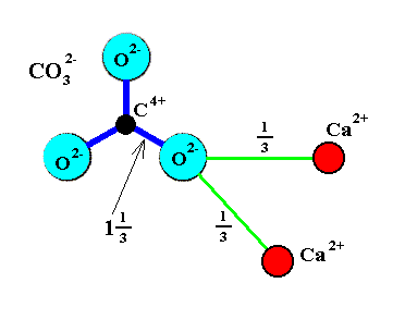
A n i s o d e s m i c b o n d i n g is found in crystals containing small, highly charged cations. Concider the mineral Calcite (CaCO3), with which we are going to occupy ourselves below : Carbon (C) is a small cation with +4 charge that coordinates with three O2-. The electrostatic valence bond (EVB) strength of the C--O bonds is therefore 4/3 = 1.33. The Ca2+ is in 6-fold coordination with these same O2- anions with an EVB of 2/6 = 1/3. Each O2- bonds with two Ca2+ cations so the total EVB reaching each Oxygen is 2 (See Figure 1). We see that the two-valency of Oxygen is in this case unevenly distributed around the Oxygen atom (4/3 goes to Carbon, 1/3 to a Ca atom and another 1/3 to a second Ca atom). The Oxygen anions are more strongly bonded to the Carbon than to the Calcium. As a consequence, distinct CO32- structural anionic groups are formed.
Figure 1. Anisodesmic carbonate (CO32-) group. Each O--C bond occupies one and one third of the available - 2 charge on Oxygen. Only two-thirds of a charge on the Oxygen is available to bond with other cations such as Ca2+.
Black disc = Carbon. Red disc = Calcium. Light blue disc = Oxygen.
( Redrawn from NESSE, W., 2000, Introduction to Mineralogy )
With all this we are now ready to delve (further) into the structural aspects of Calcite, in order to find its Complex Motif.
The Complex Motif of Calcite
The mineral C a l c i t e is one of the two crystalline varieties in which the substance CaCO3, Calcium carbonate, can occur. The other one is the mineral Aragonite.
The point symmetry of Calcite crystals is 3* 2/m, which means that they belong to the Ditrigonal-scalenohedric Crystal Class of the Hexagonal Crystal System (Rhombohedric Division). The Space Group is R 3* 2/c, which means that there is a c-glide present in the Calcite structure, i.e. three glide planes containing the c-axis.
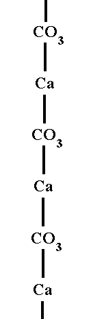
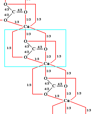
The essential structural element in all carbonate minerals (and thus also in Calcite) is the CO32- anionic group. It consists of one Carbon cation that coordinates with three Oxygen anions. Carbon, with its +4 charge, commands two-thirds of the net -6 charge of the three Oxygen anions with which it coordinates. These Oxygen anions are therefore more strongly bonded to the central C4+ cation than to any other cations in the mineral structure. Further, an Oxygen anion in one CO32- group cannot also be shared with another CO32- group, because that would imply the configuration C-O-C in which one bond strength is 4/3, leaving only 2/3 for the other bond strenght, while the latter should also be 4/3. The structure of all carbonates must therefore be based on CO32- groups that are bonded laterally through various cations (in the case of Calcite this is Calcium).
The CO3 groups lie in planes at right angles to the 3-fold (c) axis, and the Ca ions, in alternate planes, are in 6 coordination with Oxygens of the CO3 groups. Each Oxygen is coordinated to a Carbon ion within its own layer, i.e. to a Carbon ion at the center of its CO3 group, and to two Ca ions, one above and one below it. The next Figure illustrates the alternation of Ca cations with CO3 anions in the Calcite structure.
The next Figure shows in what way the Ca ions and Carbonate ions are connected to each other, resulting in a complete satisfaction (saturation) of all the valences involved. Note that the image concerns chemical connections, it does not display stereometric relationships (See also Figure 1).
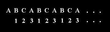
C a l c i t e belongs to the so-called rhombohedral carbonates. They can be derived from the Halite (NaCl) structure, with CO3 groups in place of Cl, and M2+ (in which M can be Calcium (Ca), Magnesium (Mg), etc.) in place of Na. The fact that we here have to do with planar triangular anions ( = ions that go, in electrolysis -- to the positive electrode, the anode, because these ions are themselves negatively charged ), in our case CO32+ groups, accounts for the fact that the structure is not cubic (like in Halite) but rhombohedral : The cube is shortened along one of its 3-fold axes (going from corner to opposite corner) to form a rhombohedron, and the plane of the triangular CO3 groups is perpendicular to this axis, which has now become the c-axis. As a result of this geometry, the CO3 groups effectively consist of a simple close-packed layer of oxygen anions with C (Carbon) occupying selected triangular sites within the layer. Successive layers are offset so that the p o s i t i o n of the C atoms is equivalent to cubic close packing (ABC-structure), i.e. their position is repeated every third layer :
Although the p o s i t i o n of the C atoms is repeated in every third CO3 layer, the corners of the triangular CO3 groups alternate by a mirror plane every layer, i.e. the o r i e n t a t i o n alternates every layer. This is because of the mentioned c-glides :
The result is that an exact duplicate layer of CO3 groups is repeated only every sixth layer. The unit cell must be six CO3 layers thick or about 15 to 17 Angstrom along the c-axis ( NESSE, W., Introduction to Mineralogy, 2000, p. 327/8 ).

If we, in the above Figure, go along the c-axis (from top to bottom), the first entity we encounter is a Calcium ion (at the tip of the depicted rhombohedron), then we encounter a CO3 group (in the center of the rhombohedron), and, finally again a Calcium ion.
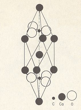
Figure 4. Unit cell of the structure of Calcite, CaCO3.
The unit cell (which is an elongated rhombohedron) contains two differently oriented CO3 groups, one situated above the central Calcium ion and one below it. The central Calcium ion corresponds to the Calcium ion at the lower end of the rhombohedron of Figure 2. This unit cell contains 8x1/8+1=2 Ca atoms and 2 CO3 groups, and thus this unit cell contains two formula units of Calcium Carbonate (CaCO3).
( Adapted from STRÜBEL, G., Mineralogie, 1977 )
The relation of the (cleavage) rhombohedron as depicted in Figure 3, to the elongated rhombohedral unit cell depicted in Figure 4 is as follows :
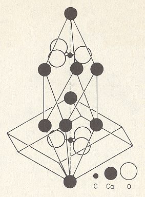
Figure 5. Unit cell of the structure of Calcite, CaCO3, in relation to the cleavage rhombohedron. We can imagine two such rhombohedrons placed on top of each other (with one Ca in common). Here a lower cleavage rhombohedron is depicted. Above we had described the upper cleavage rhombohedron in relation to the unit cell.
( After STRÜBEL, G., Mineralogie, 1977 )
The (elongated) rhombohedral unit cell fits in a larger hexagonal unit cell having (as empty building block) the shape of a hexagonal prism :
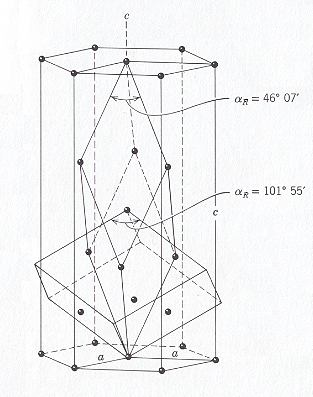
Figure 6. Two unit cell choices (elongated rhombohedron and hexagonal prism) of the structure of Calcite, CaCO3, in relation to the cleavage rhombohedron. The extra elements of the cleavage rhombohedron falling within the hexagonal prism should be repeated within the outline of a second cleavage rhombohedron on top of the first one (with a Calcium ion in common).
( After HURLBUT, C. & KLEIN, C., Manual of Mineralogy, 1977 )
As we've said the Calcite structure consists of alternate layers of Ca cations and CO3 anions. In all this, the layer of CO3 triangles shows itself to be an alternation of differently oriented CO3 triangles, as is depicted in Figure 2 (Two orientations are involved). And this means that the Ca sequence also has within it that same alternation, because -- as a consequence -- the surroundings ( = the CO3 triangles) of the Ca's alternate. So each layer comes in two alternating varieties. Let us indicate the stacking position of the Carbon ions (that lie in the center of each CO3 group) as A B C (i.e. a stacking according to the ABC-structure). But because they (with respect to the orientation of the CO3 triangles) come in two alternating varieties we must indicate the stacking of those Carbon ions as
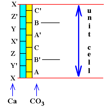
Figure 6a. Alternation of Ca-layers and CO3-layers, and within each layer an alternation in turn. The unit cell thickness is indicated. Only two CO3 groups, namely B' and B, fall within the confines of the unit cell. Their position is identical within the stacking sequence -- Both occupy B-positions -- but their orientation is different ( indicated by the absence and presence of a ' sign ). Compare with Figure 4 : The lower X and upper X in the present Figure correspond to the lower and upper Ca in Figure 4.
X' in the present Figure corresponds to the central Ca ion in Figure 4.
B' and B in the present Figure correspond to the two CO3's in Figure 4.
In the above Figure we can see that the unit cell is six CO3 layers (or, Ca layers for that matter) thick. As depicted, the unit cell's thickness contibution by the Ca's is :
In order to find the Complex Motif of Calcite, i.e. the translation-free motif of the Calcite crystal structure, we first eliminate all simple translations (which are responsible for the periodic repetition of the unit cell). What is left is evidently one unit cell as depicted in Figure 4. In this unit cell there is still a translational element present (which must also be eliminated) : We can detect this element as the translational element of the c-glide evident in the different orientation of the two CO3 triangles which fall within the confines of the unit cell.
The next Figure depicts an extention of the Calcite structure such that two unit cells (with one Ca atom in common) are visible.
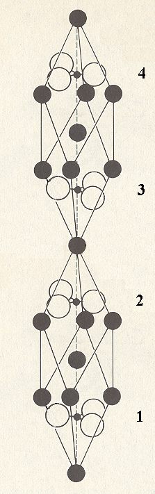
Figure 7. Two unit cells of the structure of Calcite, CaCO3. They share one Calcium atom. The CO3 triangles that fall within the confines of the two unit cells are numbered. We can see that their orientation alternates, indicating the presence of a c-glide.
The c-glide involves a reflection (of the whole structure) immediately followed by a translation (of the whole structure). We must now undo this translation. We can do this (conceptually) by making a copy of those unit cells (in fact we must make a copy of the whole structure) and shifting one copy with respect to the original as indicated in the next Figure.

Figure 8. Two unit cells of the structure of Calcite, CaCO3, and a copy of these unit cells shifted with respect to the original as indicated. The length of the shift is equal to 1/2 c, i.e. equal to half the length of the unit cell measured along the c-axis.
After the shift of the copy has been accomplished we must superimpose both images. When we now focus on one unitcell again (See next Figure), the we realize that the resulting image contains twice as much atoms as the original unit cell : while one unit cell (Figure 4) contains two formula units of Calcium Carbonate (CaCO3), the new image contains four such formula units.
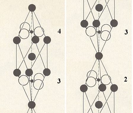
Figure 9. Concentrating on the area involved by one unit cell.
The next Figure shows the unit cell of Calcite and what must be added to this unit cell content to obtain the Complex Motif.
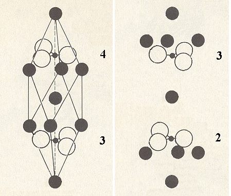
Figure 10. The unit cell of Calcite (left) and what must be added (right) to its content to obtain the Complex Motif.
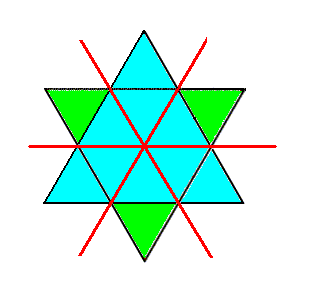
When the two images of the above Figure are properly superimposed upon one another we get the Complex Motif consisting of four formula units of Calcium Carbonate. The c-glide (three, making angles with each other of 1200) is now transformed into a set of three mirror planes parallel to the c-axis and containing this axis. Although the CO3 triangles all by thenselves form six-fold structures, the structure as a whole (i.e. the stucture of the Complex Motif) remains 3-fold because in the superimposed image the Ca atoms under 4 (left image of Figure 10) do not coincide with the Ca atoms above 3 (right image), and the Ca atoms above 3 in the left image do not coincide with the Ca atoms below 2 (right image), and after the superposition the upper set of Ca atoms consists of two groups (each comprising three atoms), and these two groups correspond qua arrangement of their atoms precisely with the two groups of Ca atoms in the original unit cell, one above the central Ca atom and one below. And because we know that the latter are in accord with a 3-fold rotation axis, we now know that also in the new image (obtained by superposition) a three-fold symmetry reigns. Also the center of symmetry remains after the superposition (Recall that a 3* axis is equivalent to a 3-fold rotation axis + center of symmetry). Finally the 2-fold axes and the mirror planes perpendicular to them are also preserved. The symmetry of the Complex Motif is therefore 3* 2/m. The geometric solid expressing this symmetry is the Rhombohedron and the promorph of crystals of Calcite is therefore belonging to the Scalenoidea rhomboedra (Stauraxonia homopola scalenoidea).
In the next document we will determine the Complex Motif of crystals of the silicate mineral Beryl.
To continue click HERE to proceed further with the preparation to the Promorphology of 3-D Crystals.
e-mail :

back to retrospect and continuation page
back to Internal Structure of 3-D Crystals
back to The Shapes of 3-D Crystals
back to The Thermodynamics of Crystals
back to Introduction to Promorphology
back to Anaxonia, Homaxonia, Polyaxonia
back to Protaxonia : Monaxonia
back to Stauraxonia heteropola
back to Homostaura anisopola, Heterostaura
back to Autopola oxystaura and orthostaura
back to Allopola (introduction)
back to Allopola amphipleura and zygopleura
back to the Basic Forms of Cells I
back to the Basic Forms of Cells II
back to the Basic Forms of Organs
back to the Basic Forms of Antimers
back to the Basic Forms of Metamers
back to the Basic Forms of Persons
back to the Basic Forms of Colonies
back to the first part of the Preparation to the Promorphology of Crystals
back to the second part of the Preparation to the Promorphology of Crystals
back to the third part of the Preparation to the Promorphology of Crystals
back to the fourth part of the Preparation to the Promorphology of Crystals
back to the fifth part of the Preparation to the Promorphology of Crystals
back to the sixth part of the Preparation to the Promorphology of Crystals
back to the seventh part of the Preparation to the Promorphology of Crystals
back to the eighth part of the Preparation to the Promorphology of Crystals
back to the ninth part of the Preparation to the Promorphology of Crystals
back to the tenth part of the Preparation to the Promorphology of Crystals
back to the eleventh part of the Preparation to the Promorphology of Crystals
back to the twelfth part of the Preparation to the Promorphology of Crystals
back to the thirteenth part of the Preparation to the Promorphology of Crystals
back to the fourteenth part of the Preparation to the Promorphology of Crystals
back to the fifteenth part of the Preparation to the Promorphology of Crystals
back to the sixteenth part of the Preparation to the Promorphology of Crystals
back to the seveneenth part of the Preparation to the Promorphology of Crystals
back to the first part of the Preparation to the Promorphology of 3-D Crystals
back to the second part of the Preparation to the Promorphology of 3-D Crystals
back to the third part of the Preparation to the Promorphology of 3-D Crystals