preparation
3-D Crystals
I
REMARK : When the reader feels satisfied with our established theoretical foundation (done in the previous two documents) that allows (single, non-twinned) Crystals to be promorphologically assessed, he or she can skip all the following, and directly proceed with The Promorphology of Crystals.
Three-dimensional Crystals
Three-dimensional crystals, of which of course our Promorphology of Crystals is all about, are much harder to grasp with respect to the determination of the c o m p l e x m o t i f than 2-D crystals are. Much of the drawings, one could set up, in order to depict the structural features of three-dimensional crystals are not expected to be very instructive because it is hard (and, strictly speaking, impossible) to display 3-D features on a 2-D drawing surface. So we will limit our expositions to just a few examples. These examples are geared to show how we must visualize the c o m p l e x m o t i f that emerges after the elimination of all translations. The symmetry of this complex motif is then the promorph (basic form) of all the (3-D) crystals of the given (3-D) Crystal Class. This promorph will then be displayed by a geometric solid that immediately shows the whole symmetry content of the promorph. This symmetry content is, for all 3-D crystals, already given by their point symmetry (and on the basis of that, by their allocation to a certain Crystal Class). So in the ensuing documents about actually assessing the promorphs of 3-D crystals, we just have to look for their point symmetry (which is -- as the present and previous documents demonstrated -- equal to the symmetry of the complex motif), and draw the actual geometric body that expresses this symmetry fully geometrically.
There are only 14 patterns of equivalent points that can fill three-dimensional space. With "equivalent" is meant that the surroundings of each point of such a pattern are identical. Such a point pattern is called a lattice, i.e a point lattice. In the case of 3-D lattices we call them Bravais lattices. Such a lattice is conceived to be extended indefinitely. If you were living in such a universe of identical points, and be stationed at one of them, and if you were, while firmly asleep, sneakily transported to another point, then, when you awake, there is nothing in your surroundings that could indicate your transposition. Your world looks exactly the same as it did before the transposition took place. That's what it means that the points of a Bravais lattice are all the same.
When we associate chemical motifs, for instace atoms, ions, groups of atoms, complex ions or molecules, with these points, then we get a p e r i o d i c structure in which certain chemical units are repeated such that the orientation of these units is the same throughout the structure. So the ordering of entities according to a lattice (for the 3-D situation this is a Bravais lattice) guarantees the emergence of a periodic structure. When these entities are of a chemical nature, then we have a
3-D c r y s t a l.
When we have to do with crystalline chemical compounds, then different atomic species could be (but must not necessarily be) imagined to be represented by lattice points. But in this case we must have to do with s e v e r a l (interpenetrating each other) lattices instead of just one, because in this case the points represent different chemical motifs, i.e. their surroundings differ, so they are NOT equivalent. So we have to imagine there being several lattices present in such a way that the points of one such lattice are equivalent among each other (they are all associated with one and the same chemical motif), and that the points of the other lattice are in the same way equivalent, they all are associated with one and the same chemical motif, which is however different from the motif that is associated with the points of the first lattice.
And even in the case of crystals consisting of just one chemical motif, say one atomic species, these motifs can arrange themselves such that they do not form a genuine lattice, i.e. one of the 14 Bravais lattices. They form t w o such lattices, interpenetrating each other, and shifted over a certain distance, with respect to each other. This we see, among others cases, in the Hexagonal Close-packing of atoms : These atoms would be expected to behave like little spheres which attract their fellows in ALL directions. Each atom would collect around it as many of its fellows as it could, as close to it as possible : On top of a first layer (A) of contiguous spheres (supposing to be atoms) there is another layer (B) of contiguous spheres lying in the hollows of the first layer. Then there is a third layer of contiguous spheres, lying on top of the second layer, in such a way that the individual spheres of this third layer lie exactly above the spheres of the first layer (A). This means that the first layer is exactly repeated in the third layer. Next there is a fourth layer, lying on top of the third layer, but such that its individual spheres lie exactly above those of the second layer (B), etc. Such a form of close-packing of spheres we call an AB-structure, it consists in fact of a stacking of layers of spheres according to ABABABABABABAB.... .
REMARK : Another type of close-packing of spheres is the ABC-structure. In such a structure the individual spheres of the third layer (C) neither lie exactly above those of the first layer, nor exactly above those of the second layer (because there are two alternative ways of adding the third layer, and now the other alternative is chosen). The spheres of a fourth layer, supported by the third layer, however, lie exactly above those of the first layer again, and thus the first layer (A) is repeated in the fourth layer. The individual spheres of the fifth layer lie exactly above those of the second layer (B), etc. So we have a stacking of layers according to ABCABCABCABC.... . In both arrangements of close-packing of spheres (AB and ABC) each sphere is in contact with twelve others. The ABC-structure is called Cubic Close-packing (while the AB-structure is called Hexagonal Close-packing). There is an infinity of stacking modes conceivable. For example stackings in which the period of repetition is longer, say 5 as in ABABC. As soon as there is no such repetition the arrangement is still close-packed but not regular anymore and thus not crystalline.
The Hexagonal Close-packed arrangement (the AB-structure) is adopted by the atoms of the metal Magnesium. The corresponding l a t t i c e t y p e is called the Magnesium-type.
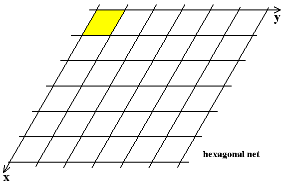
This stacking is an ordering of atoms (in the present case all of the same species) according to two interpenetrating hexagonal lattices. The Hexagonal Lattice is one of the Bravais lattices. It consists of a vertical stacking of two-dimensional hexagonal nets (a net is a 2-D point lattice). The next Figure shows such a hexagonal net.

Figure 1. The two-dimensional hexagonal lattice (net). The net consists of a pattern of equivalent points. These points are (here in the Figure) represented by the intersections of the lines (These lines themselves do not belong to te net, they only visualize the hexagonal arrangement of the lattice points). The net is obtained by regularly and indefinitely repeating a point along the Y-direction. In this way a row of regularly spaced points is obtained. This row will then be repeated along the X-direction. The repeating distance is the same as that of the points in the row (Y-direction). The angle between the X-direction and the Y-direction is 600. The net so obtained can (also) be seen as a repetition in two directions (X and Y) of a rhombus (yellow). This can be considered to be a possible choice of a two-dimensional unit cell. Another possible choice is a hexagonal unit cell (See Figure 3).
We can draw an additional set of (parallel) lines to aid visualisation (we will then obtain a triangulation of two-dimensional space). Still, the intersections are the lattice points of the hexagonal net :
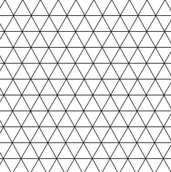
Figure 2. The two-dimensional hexagonal lattice (net). The net consists of a pattern of equivalent points. These points are (here in the Figure) represented by the intersections of the lines. As compared with the previous Figure we have added another set of parallel lines (All the lines do not belong to te net, they only visualize the hexagonal arrangement of the lattice points).
The next Figure indicates two possible two-dimensional unit cells : a rhombus and a hexagon. The net can be seen as formed by a regular repetition of such a unit cell. In the present case this unit cell represents an e m p t y b u i l d i n g b l o c k of the structure.
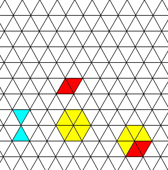
Figure 3. The two-dimensional hexagonal lattice (net). The net consists of a pattern of equivalent points. These points are (here in the Figure) represented by the intersections of the lines. Two triangles of the triangulated 2-D space are indicated (light blue). Such a triangle is not a unit cell because, although it is repeated, it is not repeated in the same orientation throughout the net. A rhombus (red) representing a unit cell is indicated. Another unit cell choice -- a hexagon -- is also indicated (yellow). The rhombus is a part of such a hexagon.
Still larger unit cells could be chosen, as the next Figure illustrates.
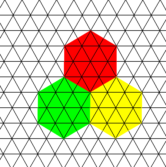
Figure 3a. A large unit cell can be chosen (whenever that turns out to be convenient). The figure shows that such a unit cell indeed builds up the structure by periodically being repeated. This (2-D) unit cell consists of 13 lattice points. If we only admit the center node and the six outer nodes (lying in the hexagon's corners) as lattice points, then we have to do with the same hexagonal lattice, but with its net being coarser (which makes no difference at all with respect to symmetry).
In Figure 4 (below) we have placed m o t i f s (small red discs) into the point lattice. This means that each lattice point is associated with a motif. These motifs are all equivalent. They form (together with their own surroundings) the surroundings of the lattice points. These surroundings are all identical. We can think of these motifs as 'atoms' of a certain species. In fact the atoms in a crystal lattice are in physical contact with each other, which means that we should have indicated them as contiguous discs (and in 3-D as contiguous spheres). See the next Figure.
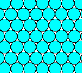
Figure 3b. Atoms in a crystal are in physical contact with each other. So we should depict a close-packed layer of them as is done in this figure.
It is however much more convenient to represent the atoms only by their central areas, i.e. as little discs (spheres) connected by the auxiliary lines of the net, as we indeed have done in Figure 4, and also in all the next Figures. Another way of interpreting all these Figures is that we imagine the space between the atoms to be e x t e n d e d equally, i.e. uniformly, in all directions, resulting in the atoms to become separated from each other, i.e. they are now lying further apart (they are not contiguous anymore). For our purposes this is legitimate, because the s y m m e t r y of the structure is not affected in any way by such an uniform extention of the interstitial space. And in our undertaking it is only the symmetry that matters. In other cases it could be necessary to superimpose motif parts (in the process of the elimination of translations) in order to obtain the Complex Motif, and with it to obtain the complete tectological aspect of the given crystal. In yet other cases we have to consider half motifs. So the Complex Motif is a highly abstract entity. Nevertheless every crystal has genuine, i.e. not abstract, but concrete, tectological features, as they are present in every chemical substructure actually present in the crystal. But these chemical substructures each for themselves often do not display the complete point symmetry of the crystal, because they often are just parts of a motif that is as it were unravelled (i.e. disentangled) by glide planes or screw axes. So we have, conceptually, to put these motifs together again, resulting in complete motifs that display the full point symmetry of the crystal.
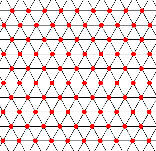
Figure 4. The two-dimensional hexagonal lattice (net), furnished with motifs (small red discs). The interstitial space is imagined to be extended uniformly, causing the atoms (which are the motifs in the usual sense) to stand apart from each other by some didtance (of course the t o t a l motifs, i.e. the complete surroundings of the lattice points, are still contiguous because the (extended) interstitial space belongs to the total motif ).
The pattern of spheres in Figure 4, must, according to what has been said, be interpreted as follows :
The hexagonal lattice, as shown in the above Figures, is, as such, a 2-dimensional lattice (net). When we now repeat this whole lattice along a direction Z perpendicular to the 2-D net, i.e. perpendicular to direction X as well as to direction Y, we get a 3-D lattice, i.e. one of the 14 possible 3-D point lattices called Bravais lattices. And now we can interpret the previous Figure as displaying the first layer (A) of a close-packing of identical spheres. Each sphere (atom) is surrounded by six nearest neighbors. If we now want to add a second layer of spheres, these added spheres should come to lie in the hollows (dimples) between the spheres of the first layer (this is because, in our case, the atoms want to be as close as possible to each other -- Recall that our conceptually extended dimples still are not supposed to physically accomodate for whole spheres, only for a part of each of them, causing them to form a second layer on top of the first layer). So because the added spheres associate themselves with dimples between the spheres of the first layer, the second layer (B) ends up to be shifted horizontally with respect to the first layer (A).
And now it is clear that in doing so we add a second l a t t i c e, identical to the first one but shifted a certain distance with respect to the first lattice. The next Figure shows a part of this second hexagonal lattice furnished with the same species of atoms. We have used a different coloring to distinguish it from the first one (Their difference is not one with respect to content or geometry, but one of positioning of it with respect to the first lattice).
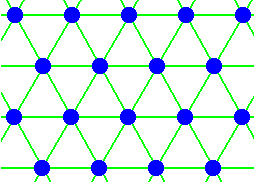
Figure 5. Part of the same hexagonal lattice (net) as in the previous Figure, furnished with the same motifs.
In the next Figure we place this second layer (B) of atoms on top of the first layer (A), such that the individual atoms of the second layer come to lie in the hollows between the atoms of the first layer. Next we add the third layer according to the AB stacking principle of Hexagonal Close-packing, which means that the individual atoms of this third layer come to lie exactly above those of the first layer. This implies that we do not need to draw this third layer, because the first and third layers coincide exactly when seen from above. See next Figure.
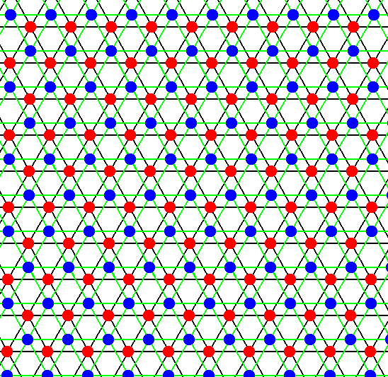
Figure 6. Superposition of two identical lattices furnished with the same atomic species. The second lattice is shifted with respect to the first along the longer diagonal of a rhombus. The motifs of this second lattice end up exactly above the centra of each triangle of the first net, triangles that are constituted by three atoms of the first layer. The third net (represented by the third layer) fully coincides with the first net, while the fourth net fully coincides with the second, implying that only two interpenetrating nets (lattice) are involved. Or in other words : The layers A in the sequence ABABABABAB .... together form one and the same hexagonal 3-D lattice (Hexagonal Bravais lattice)(we can call it the A-lattice), while the layers B in that same sequence together form a second hexagonal 3-D lattice (Hexagonal Bravais lattice)(we can call it the B-lattice). These two lattices, as they are furnished with atoms, interpenetrate each other as indicated.
So now, in Figure 6, we have constructed the arrangement of identical spheres (atoms) according to the AB-stacking principle. This arrangement is called the Hexagonal Close-packing of identical spheres (Another frequently occurring regular close-packing is the Cubic Close-packing, i.e. a stacking of layers according to ABC).
Figure 6 accordingly depicts a three-dimensional atomic arrangement as it is for example in the metal Magnesium. So in fact it depicts the internal structure of a crystal. This structure can be described as a periodic ordering of atoms according to two interpenetrating three-dimensional hexagonal point lattices. One such lattice is formed by the totality of all the A-layers, the other by the totality of all the B-layers. The only difference between these two lattices as they are furnished with atoms, is their mutual position : they are shifted with respect to each other along the longer diagonal of the rhombus, as indicated in the Figure, and in addition to that they are shifted half a vertical unit cell length along the c-axis. Figure 6 is such that we look down along the crystal's c-axis, i.e. our direction of view is perpendicular to the layers.
The two (equal) lattices relate to one another according to the next Figure. There the view direction is perpendicular to the c-axis.
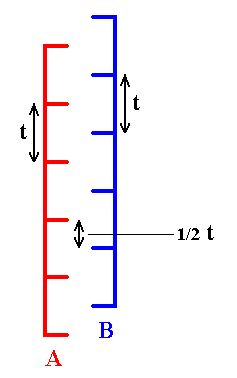
Figure 7. The two lattices (A and B) of Figure 6, seen perpendicular to the c-axis. Of course the lattices extend indefinitely in all three directions of space. The transverse horizontal line segments symbolize the layers (of spheres). The simple vertical translation distance is given by t. This means that the simple translation distance (as distinguished from glide or screw translations) of each lattice along the c-direction is t. In the vertical direction (c-direction) the lattices are shifted by half a simple translation distance, 1/2 t .
In the structure as depicted in Figure 6 we can detect six-fold s c r e w a x e s of the type 63. Let us first show such an axis :
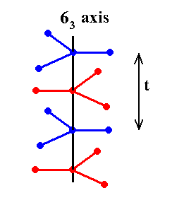
Figure 8. A six-fold screw axis of the type 63. The structure displaying this axis must imagined to be extended indefinitely in both vertical directions. If we rotate this structure about the axis (vertically drawn in the Figure) by 600 immediately followed by a translation (linear shift) along that axis, and with translation distance 1/2t, then we end up with precisely the same structure, and this means that the structure has a 63 (screw) axis. .
In the lattices (A and B) of Figure 6 it is easy to locate these 63 (screw) axes. We show this for a part of the lattice in the next two Figures.
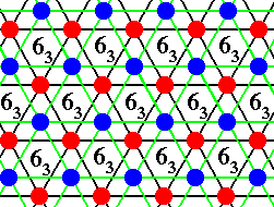
Figure 8. Location of six-fold screw axes of the type 63 in the structure of Figure 6 (The AB-structure) .
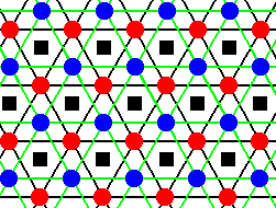
Figure 8a. Location of six-fold screw axes of the type 63 in the structure of Figure 6 (The AB-structure), indicated by small black squares (not to be confused with the symbol for a 4-fold axis) .
In addition to the screw axes given above, the structure also has g l i d e p l a n e s (of the type c), in three equivalent directions. The glide planes are given in the next three Figures, by means of straight blue lines. These lines can be seen as the intersections of the glide planes with the plane of the drawing, so the glide planes are perpendicular to the plane of the drawing, and parallel to the c-axis. We can read these glide planes as follows (where we follow one motif) : A blue motif -- this is a sphere belonging to the B-layer -- is reflected across the glide plane (in the drawing that is : across the blue line) immediately followed by a translation perpendicular to the plane of the drawing, i.e. parallel to the c-axis, by a translation distance of 1/2t. When we do this with the whole structure as depicted in Figure 6, then that structure will be mapped onto itself, which means that indeed the glide planes are a symmetry element of the structure, i.e. those glide planes belong to the structure's symmetry content. The next three Figures depict the position of the glide planes (perpendicular to the plane of the drawing) in the three directions. They are called c-glides because the translations are parallel to the c-axis (and in our Figure perpendicular to the plane of the drawing).
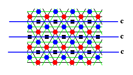
Figure 9. Location of c-glide planes in the structure of Figure 6 (The AB-structure), indicated by blue lines.
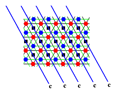
Figure 10. Location of c-glide planes in yet another direction in the structure of Figure 6 (The AB-structure), indicated by blue lines.
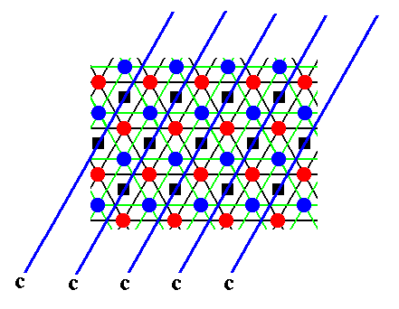
Figure 11. Location of c-glide planes in a third (and last) direction in the structure of Figure 6 (The AB-structure), indicated by blue lines.
The structure of Figure 6, i.e. the AB-structure or Hexagonal Close-packed Structure, corresponds to the Space Group P 63/m 2/m 2/c. We recognize the six-fold screw axes (63) and the glide planes (c) in the Space Group symbol. From this symbol we can deduce the point symmetry of the structure (its Point Group, and with it its allocation to a certain Crystal Class) : When we eliminate all translations, then all screw axes become ordinary rotation axes, and all glide planes become mirror planes. The letter P in the symbol stands for primitive lattice. A primitive lattice is based on a unit cell that has points only at its corners. Indeed each lattice of our structure (A and B, which are identical) can be based on a rhombic prism of which the top and bottom faces are a rhombus which we already knew as a possible 2-dimensional unit cell for the 2-D hexagonal net. These top and bottom faces, which are parallel to each other, are connected by straight lines perpendicular to those top and bottom faces, and so making up a unit cell with points only at its corners. Both lattices, A and B, can be based on such a primitive unit cell indicated as P in the Space Group symbol. So this letter P stands for the simple translations as they are determined by the edges of that unit cell. So after elimination of all translations also P disappears from the symbol. And as we've said glide planes become mirror planes (m), and screw axes become ordinary rotation axes. Thus what remains -- the translation-free residue of a possible family of Space Groups -- is : 6/m 2/m 2/m. And this is the point symmetry as we find it in crystals belonging to the Dihexagonal-bipyramidal Crystal Class of the Hexagonal Crystal System. So we know already that our c o m p l e x m o t i f -- i.e. the chemical motif that, while having itself a tectological structure (= a non-periodic structure), is the natural cause for the tectological aspect of (single, non-twinned) crystals -- must have the symmetry 6/m 2/m 2/m, that can geometrically be fully represented by a regular hexagonal bipyramid. This six-fold bipyramid is a species of the (Stauraxonia) Isostaura polypleura.
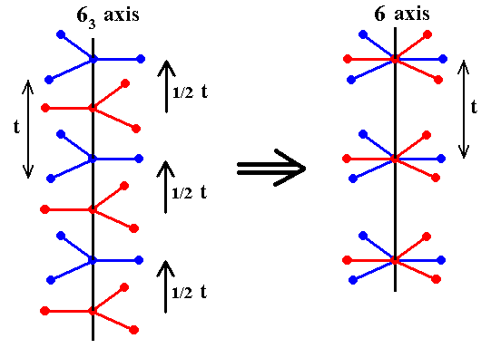
Figure 12. Transformation of a 63 screw axis into an ordinary 6-fold rotation axis in virtue of the elimination of the screw translations ( 1/2 t ). The simple translations ( t ) remain present ( These simple translations are parallel to the c-axis. Also the other simple translations, each parallel to a horizontal crystallographic axis, still remain present ).
The c-glides, that we have illustrated above, involve precisely the same translations as the screw axes do. So with the elimination of the screw translations we have, at the same time, eliminated the glide translations. The next Figure symbolizes the elimination of the translation component of the c-glide. The short horizontal line segments symbolize the (stacking of the) layers of spheres. The structure must be imagined to be extended indefinitely. Here we see, as we did also in Figure 12, that all the A-layers are going to coincide with the B-layers.
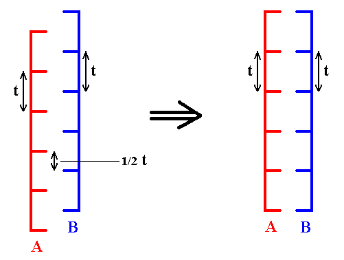
Figure 13. Elimination of the glide translations involved in the c-glides. The A-layers shift along the c-axis by 1/2 t (or, so one can call it, 1/2 c), resulting in the coincidence of the A-layers with the B-layers. The simple translations ( t ) remain present. The structures must be imagined to be extended indefinitely.
The next Figure illustrates the c-glide viewed perpendicular to the c-axis. We see the two components of this glide : a mirror reflection immediately followed by a translation.
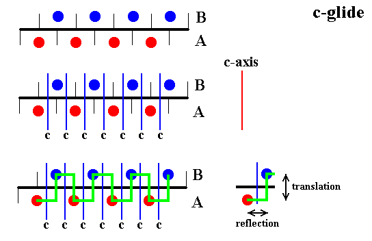
Figure 14. The c-glide of the AB-structure, as deduced from Figure 6.
Top image : Shown are two layers of spheres, the A-layer (red) and the B-layer (blue). View direction perpendicular to the c-axis. The configuration of the spheres is according to a c-glide.
Center image : The c-glide planes are shown (blue lines).
Bottom image : The operation coresponding to the c-glide is shown (green line). The motif is reflected across the glide plane and immediately translated over a distance of 1/2 t parallel to the c-axis.
If we now eliminate the translations of the c-glide, the A-layers coincide with the B-layers with respect to their level, i.e. they now lie at the same level. This is illustrated in the next two Figures. Indeed this was already accomplished by the elimination of the screw translation.
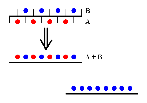
Figure 15. Elimination of the translations involved in the c-glide planes. The A- and B-layers now coincide with respect to their level. The fact that the A-layers lie on the same levels as the B-layers (they interpenetrate one another in one and the same plane) is indicated by giving all the motifs the same color.
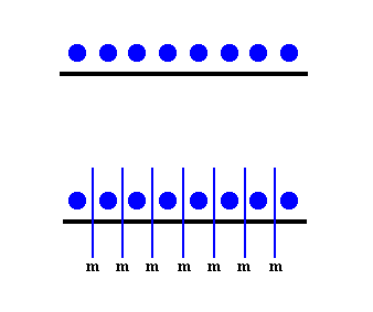
Figure 16. As a result of the elimination of the glide translations of the c-glide planes, these glide planes have become mirror planes (m).
Of course, strictly speaking, the above alignment of A-spheres and B-spheres is not possible, because the only space available for the B-spheres during stacking were the alternate dimples between the A-spheres. Because the layer of A-spheres is itself already close-packed (each sphere in that layer is immediately surrounded by other spheres : six contiguous spheres) it cannot accommodate more spheres. Nevertheless we stick to this alignment as resulting from the elimination of the glide (or screw) translations : As has been said earlier, we consider the interstitial space between the atoms as (conceptually) uniformly extended in all directions, causing these atoms to stand farther apart (and as far as we wish them to be). This is legitimate because our present discussion concerns the promorph of (3-D) crystals, i.e. their point symmetry. And this point symmetry is not affected at all by the mentioned (conceptual) uniform extention of the interstitial space.
Before we proceed further, we say something about m o t i f s and possible u n i t c e l l s ( See also the First Document that prepares for a Promorphology of Crystals, after Figure 5 there ).
A m o t i f associated with a lattice point is in fact the COMPLETE SURROUNDINGS of that lattice point. This implies that a motif, so conceived -- let us call it the t o t a l m o t i f -- has the same size, and has an equivalent content, as a possible u n i t c e l l. This means that the total motif is equivalent to a possible unit cell. All this implies that when we telescope a crystal structure back, i.e. eliminate all translations (in order to find the complex motif, and on the basis of it the crystal's tectology), we cannot push this so far as to even sqeeze a unit cell. The process stops at the unit cell (Recall that choosing a smaller unit cell than some given unit cell, has nothing to do with an elimination of translations). The smallest part of the lattice is the lattice point. And as soon as we include content to a point lattice, each lattice point is associated with its surroundings (which have, and represent, content). This surroundings are the total motif of the structure (i.e. the given point lattice provided with content). So the total motif is the smallest unity that we can get by eliminating translations, and this total motif is -- as we just saw -- equivalent to a possible unit cell. See next Figures.
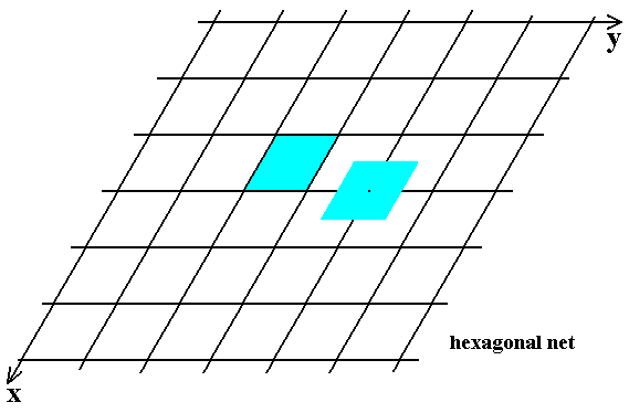
Figure 17. The Hexagonal Net (as already depicted earlier).
A possible unit cell is indicated (light blue). This unit cell coincides with a rhombus of the net. It involves four lattice points. When motifs were associated with the lattice points, four 1/4's of these motifs ( = one motif ) could be counted as to belong to the unit cell's content.
Also indicated are the COMPLETE SURROUNDINGS of a lattice point. These complete surroundings (of a single lattice point) are equivalent to the total motif. It has the same size and form as the unit cell. The surroundings of the lattice points are -- by definition -- the same with respect to each lattice point.
In the next Figure we depict the same situation as to unit cell and total motif, but here the total motif is such that we can distinguish between a motif in the usual sense, here represented by a black comma, and the total motif, i.e. the comma + its proper surroundings. But even when the surroundings of the comma are empty space, they belong to the (total) motif associated with that particular lattice point.
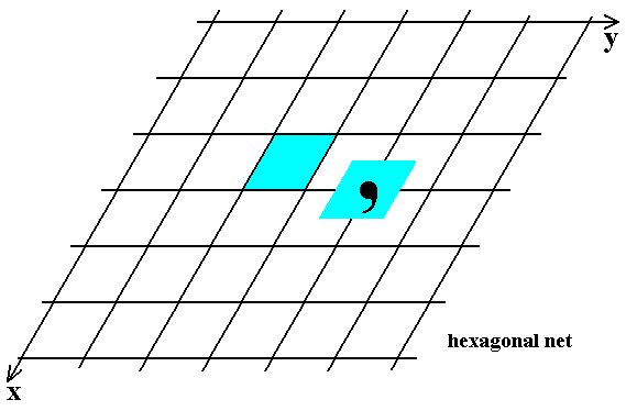
Figure 18. The Hexagonal Net.
A possible unit cell is indicated (light blue). This unit cell coincides with a rhombus of the net. It involves four lattice points. When motifs were associated with the lattice points, four 1/4's of these motifs (= one motif) could be counted as to belong to the unit cell's content.
Also indicated are the COMPLETE SURROUNDINGS of a lattice point. Now they include a comma as a motif in the usual sense. Of course these comma's occur at every lattice point, and this means that the unit cell -- as outlined -- contains four 1/4's of such a comma, which means that it contains just one comma, just like the complete surroundings of a lattice point : they also contain one comma.
All what has been said about the total motif and its equivalence to a possible unit cell, is equally valid for t h r e e - dimensional structures.
The next Figures depict possible unit cells for the AB-structure.
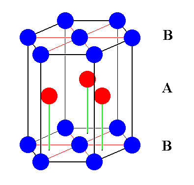
Figure 18a. A possible unit cell for the AB-structure (here, of course, with every translation in tact). This unit cell has the form of a hexagonal prism. All the motifs stand for the same atomic species. Red spheres are A-spheres (i.e. belonging to the A-layers). Blue spheres are B-spheres (i.e. belonging to the B-layers). The content of the unit cell belongs to two (identical but shifted with respect to each other) hexagonal lattices.
One third of this hexagonal unit cell can also serve as a unit cell for the structure. It is outlined in the next two Figures.
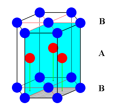
Figure 18b. A third of the hexagonal unit cell can also be chosen as a unit cell for the AB-structure. See also next Figure, where it is isolated.
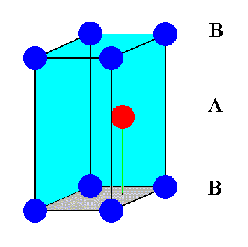
Figure 18c. One third of the hexagonal unit cell can also be chosen as a unit cell for the AB-structure. It is a rhombic prism. This unit cell contains 8 x 1/8 + 1 = 2 spheres (atoms).
In order to find the c o m p l e x m o t i f (which, while possessing itself a tectological structure, lies at the basis of the crystal's tectological aspect), we first reproduce Figure 8.

Figure 19. (=Figure 8) Location of six-fold screw axes of the type 63 in the structure of Figure 6 (The AB-structure) .
We can also depict this by indicating the 63 screw axes by small black squares (not to be confused with the symbol for a 4-fold rotation axis!), as we did earlier :

Figure 20. (= Figure 8a) Location of six-fold screw axes of the type 63 in the structure of Figure 6 (The AB-structure), indicated by small black squares (not to be confused with the symbol for a 4-fold axis) .
But, because we have eliminated the screw and glide translations, the B-layers are superimposed upon the A-layers, i.e. they now lie at the same level. Such a level is accordingly composed of A-spheres and B-spheres. What is left are identical layers of spheres lying precisely on top of each other and separated by a translation, which is the simple translation corresponding to the vertical edges of the rhombic unit cell ( The length of this translation is t, or, if one wishes to call it, c ). The next Figure illustrates this.
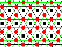
Figure 21. After elimination of the glide and screw translations the A-layers come to lie at the level of the B-layers and the six-fold screw axes ( of the type 63 ) become ordinary 6-fold rotation axes, indicated by small black squares (not to be confused with the symbol for a 4-fold axis) .
Now that the six-fold screw axes have become ordinary six-fold rotation axes, we will consider such an axis as the center of a possible complex motif. The next Figure illustrates the symmetry of our structure obtained by eliminating the glide and screw translations.
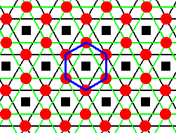
Figure 22. The symmetry content of the structure is indicated by the inscribed hexagon. This hexagon has the following symmetry content : One 6-fold rotation axis and two sets of mirror lines (three mirror lines connecting the corners of the hexagon, three others connecting the centers of its sides). Because we have such hexagons also exactly below and exactly above the present layer of hexagons (stacked in a direction perpendicular to the plane of the drawing), a possible unit of the periodic structure is a hexagonal prism. In addition to the mentioned symmetry elements this prism also possesses a mirror plane coinciding with its equatorial plane and perpendicular to the six-fold rotation axis. In this prism the mentioned mirror lines (of the hexagon) are now mirror planes, parallel to the c-axis (The c-axis is perpendicular to the plane of the drawing).
The next Figure indicates a possible t o t a l m o t i f (equivalent to a unit cell). It comprises 2 x 6 = 12 whole spheres (representing atoms of one and the same species), 6 above and 6 below.
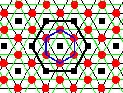
Figure 23. The symmetry content of the structure is indicated by the inscribed hexagon. A larger hexagon (thick black lines) indicates a total motif.
When we omit most of the auxiliary lines we get the following image of this hexagon.
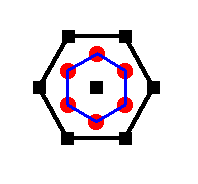
Figure 24. The larger hexagon (thick black lines). Some auxiliary lines erased. It indicates a total motif.
The next Figure demonstrates that the larger hexagon (as does also the smaller one) indeed generates the entire structure -- which had been made free of glides and screws -- when repeated periodically.
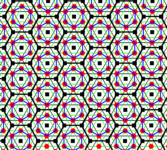
Figure 25. The hexagonal prism associated with the larger hexagon (thick black lines) is a t o t a l m o t i f associated with a lattice point, and builts up the 3-D structure (where the glide and screw translations are eliminated) when it is repeated periodically.
Also the smaller hexagons can built that same structure by periodic repetition. This is shown in the next Figure.
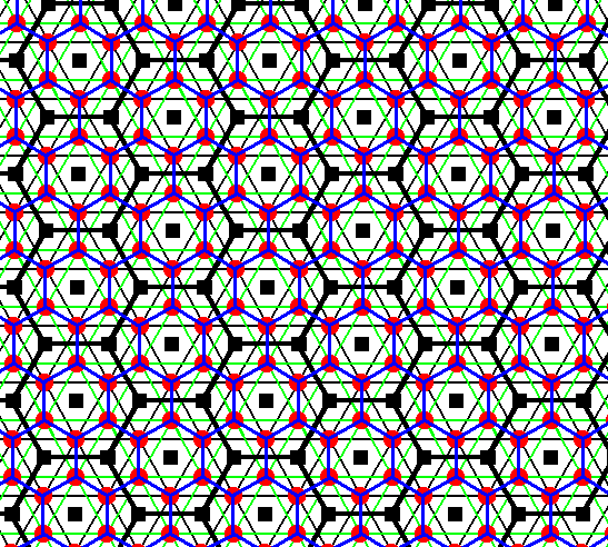
Figure 26. The smaller hexagons (blue), each accounting for six 1/6's spheres ( = one sphere ), can generate the whole structure, when they are repeated periodically.
The next Figure emphasizes (light blue) a total motif consisting of 2 x 6 = 12 (whole) spheres (six above and six below, the latter are fully masked by the former).
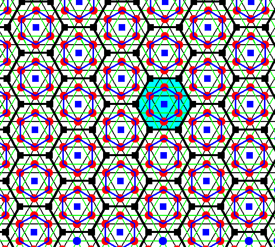
Figure 27. Indication of one total motif (light blue). The points with which each of these motifs is associated must now be interpreted as lattice points of our glide- and screw-free structure. They are represented by small blue squares. Their positions coincide with a part of the 6-fold rotation axes. Each lattice point is associated with a total motif in the following way : The total motif has the form of a hexagonal prism. The mid-point of the top face of such a prism coincides with a lattice point. The edges of the total motif coincide with six 6-fold rotation axes. The total motif contains 12 whole spheres, six above, six below.
The next Figure depicts seven such total motifs, associated with seven lattice points. These motifs are hexagonal prisms. The centra of their bottom faces correspond to seven other lattice points, lying exactly below the first mentioned seven lattice points.
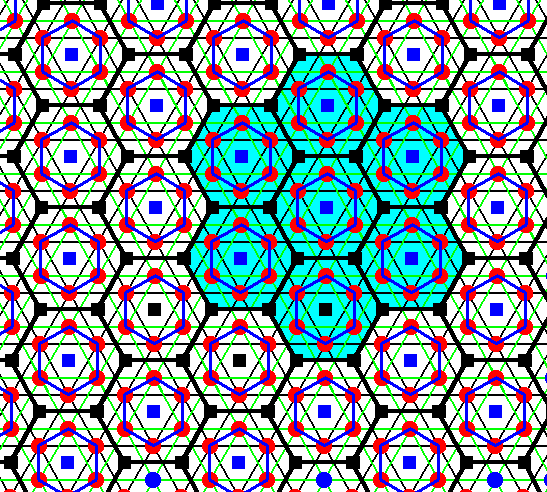
Figure 28. Seven total motifs are indicated (light blue). They correspond to seven upper lattice points. When we connect these lattice points with lines we get the outline of a possible unit cell choice. See next Figure.
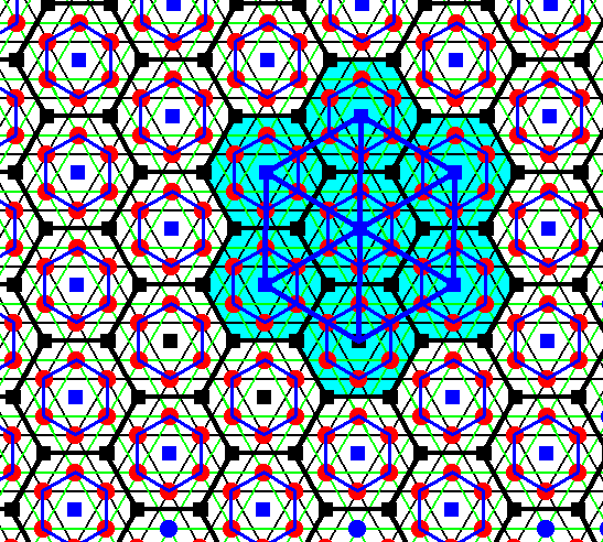
Figure 29. Seven total motifs are indicated (light blue). They correspond to seven upper lattice points. These lattice points are now connected with lines, resulting in the outline of a possible unit cell choice.
When we exclusively depict what belongs to this unit cell and leave out all what doesn't, we get the hexagonal unit cell. In the next Figure we compare this unit cell (choice) with the total motif. This -- isolated -- total motif finally emerges after eliminating all s i m p l e t r a n s l a t i o n s (after having already eliminated all screw and glide translations). Indeed, when we eliminate all simple translations we are left with one lattice point + its complete surroundings, and this is -- as we found out earlier -- equivalent to the total motif.
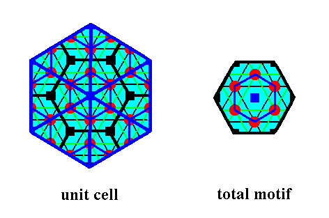
Figure 30.
Left image : The precise outline and content of the hexagonal unit cell (representing the hexagonal bravais lattice).
Right image : The total motif, as it is after elimination of all translations. It is identical to the Complex Motif.
Of course any total motif can itself also figure as a chosen unit cell of the structure.
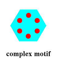
Figure 31. When we do away with all auxiliary lines and points in the above image of the Complex Motif, we get the Complex Motif as it is all by itself. It consists of two equal layers (an upper one and a lower one), each of which is composed of six spheres (atoms, of the same species) arranged according to the vertices of a regular hexagon. The two layers are situated exactly above each other, implying that in our view direction, which is parallel to the c-axis, we see only one such layer.
Included in this Complex Motif are also the proper surroundings of that motif. As such it can built the whole structure when repeated periodically.
When we strip away all auxiliary features of the unit cell as depicted in Figure 30, we end up with the following image.
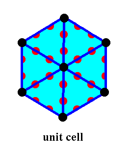
Figure 32. When we do away with all auxiliary lines and points in the above image of the unit cell, we get it as it is all by itself. It consists of two equal layers (an upper one and a lower one), each of which is composed of 18 ( 6x2x1/2 + 6 + 6 ) spheres (atoms, of the same species). The two layers are situated exactly above each other, implying that in our view direction, which is parallel to the c-axis, we see only one such layer. As can be seen in the Figure the unit cell contains some half motifs. As such this unit cell can build the whole structure when repeated periodically.
In the above Figures we see that the total motif corresponds with a l a r g e r unit cell choice, i.e. although the unit cell has the same shape as the total motif (namely a hexagonal prism -- of which we only see its top face), it is larger than the total motif. Figure 30 makes clear why this is so. If we had chosen a unit cell such that it is a third of the hexgonal unit cell, a unit cell would result having the shape of a rhombic prism, and then the corresponding total motif and that unit cell would have the same size (See Figure 17 and also Figure 3).
The total motif, as depicted in Figure 31, contains twelve whole spheres, six above, ordered according to a regular hexagon and six exactly below, also ordered according to a regular hexagon. The whole motif is accordingly ordered according to a regular hexagonal prism. AND THIS TOTAL MOTIF IS THE SOUGHT FOR COMPLEX MOTIF, and the s y m m e t r y c o n t e n t of this motif is :
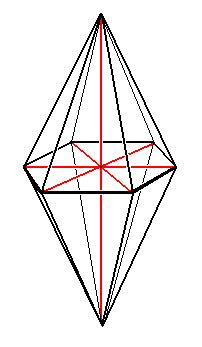
This bipyramid -- representing the symmetry of the Complex Motif -- belongs, as a regular bipyramid, promorphologically to the (Stauraxonia) Isostaura polypleura.
In the next document we will give some more examples as to how to deduce the Complex Motif that lies at the basis of the tectological aspect of the given 3-D crystal, and which legitimizes it to be considered promorphologically. When we generalize these findings we have acquired a theoretical foundation for treating all single non-twinned crystals promorphologically.
To continue click HERE to proceed further with the preparation to the Promorphology of 3-D Crystals (second part).
e-mail :

back to retrospect and continuation page
back to Internal Structure of 3-D Crystals
back to The Shapes of 3-D Crystals
back to The Thermodynamics of Crystals
back to Introduction to Promorphology
back to Anaxonia, Homaxonia, Polyaxonia
back to Protaxonia : Monaxonia
back to Stauraxonia heteropola
back to Homostaura anisopola, Heterostaura
back to Autopola oxystaura and orthostaura
back to Allopola (introduction)
back to Allopola amphipleura and zygopleura
back to the Basic Forms of Cells I
back to the Basic Forms of Cells II
back to the Basic Forms of Organs
back to the Basic Forms of Antimers
back to the Basic Forms of Metamers
back to the Basic Forms of Persons
back to the Basic Forms of Colonies
back to the first part of the Preparation to the Promorphology of Crystals
back to the second part of the Preparation to the Promorphology of Crystals
back to the third part of the Preparation to the Promorphology of Crystals
back to the fourth part of the Preparation to the Promorphology of Crystals
back to the fifth part of the Preparation to the Promorphology of Crystals
back to the sixth part of the Preparation to the Promorphology of Crystals
back to the seventh part of the Preparation to the Promorphology of Crystals
back to the eighth part of the Preparation to the Promorphology of Crystals
back to the ninth part of the Preparation to the Promorphology of Crystals
back to the tenth part of the Preparation to the Promorphology of Crystals
back to the eleventh part of the Preparation to the Promorphology of Crystals
back to the twelfth part of the Preparation to the Promorphology of Crystals
back to the thirteenth part of the Preparation to the Promorphology of Crystals
back to the fourteenth part of the Preparation to the Promorphology of Crystals
back to the fifteenth part of the Preparation to the Promorphology of Crystals
back to the sixteenth part of the Preparation to the Promorphology of Crystals
back to the seveneenth part of the Preparation to the Promorphology of Crystals