e-mail :

Sequel to the Plane Group P6mm
As we did with respect to the Plane Groups P3m1, P31m and P6, we will investigate the extension of motifs in P6mm periodic motif patterns.
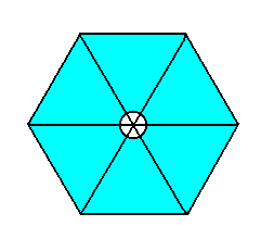
First we take a motif s.str. as we have it in Figure 7 of the previous document, isolate it, and extend it till an arbitrary size. See next Figure.

Figure 1. A motif s.str. from the P6mm pattern of Figure 7 of the previous document is isolated and arbitrarily (but uniformly) extended. The small circular central part of it belongs to the motif's structure.
Next we're going to tile the plane with such extended motifs. Thereby we do not change their initial orientations. The next Figure is the result.
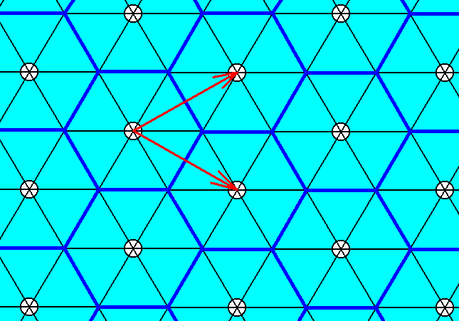
Figure 2. The plane is tiled by the extended motif of Figure 1, in such a way that the orientation of the tiles is the same as that of the motifs s.str. of Figure 7 of the previous document. Thick blue lines highlight the boundaries of the individual extended motifs and their way of tiling the plane. The corresponding tiling directions are indicated by arows. They differ from those of the mentioned Figure 7.
According to the tiling directions we can determine a hexagonal net which describes the repeating mode of a rhomb-shaped unit cell, and with it of the extended hexagonal motifs :
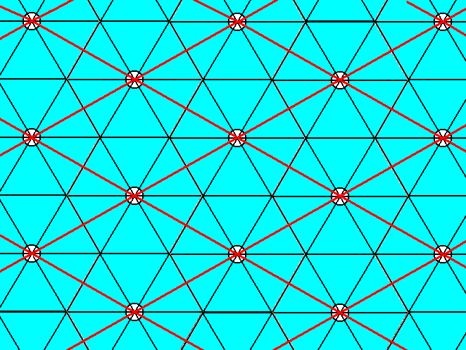
Figure 3. The pattern that was constructed by the tiling of an extended motif as described above, is such that a rhomb-shaped unit cell defines a net (of which a mesh is that unit cell) as indicated by the red lines.
Inspection of the pattern of Figure 3 reveals -- by checking its symmetry content and distribution against the symmetry diagram of the Plane Group P6mm depicted in Figure 8 of the previous document -- that its symmetry content and its distribution is still according to the Plane Group P6mm. This in contrast to what we found in the Plane Group P3m1 : extending a tri-radiate hexagonal motif s.str. and let it as such tile the plane yielded a pattern according to the Plane Group P31m.
Let us first examine the pattern of Figure 3, whether it really belongs to te Plane Group P6mm. In order to do so we will consult the symmetry diagram depicted in Figure 8 of the previous document. Thereby we must realize that our pattern as a whole is rotated by 300 with respect to the orientation of the diagram.
The mirror lines as demanded by the symmetry diagram are present as can easily be verified in Figure 3.
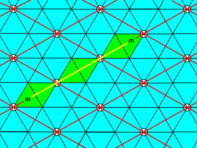
Figure 4. The pattern of Figure 3 contains mirror lines (yellow) coinciding with a unit cell edge, as demanded by the symmetry diagram for the Plane Group P6mm.
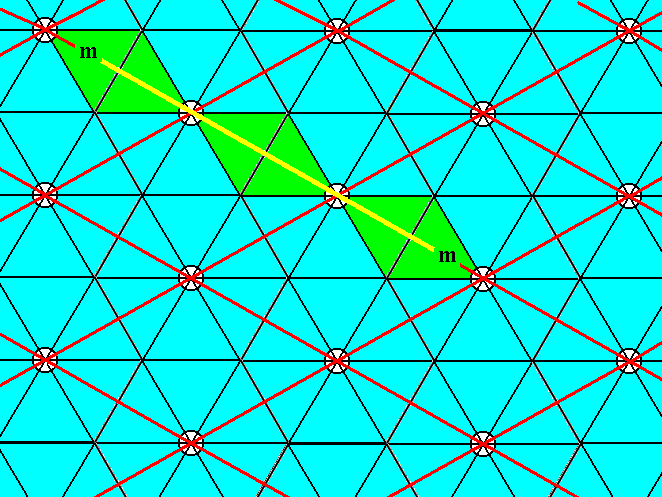
Figure 5. The pattern of Figure 3 contains mirror lines (yellow) coinciding with the other unit cell edge, as demanded by the symmetry diagram for the Plane Group P6mm.
In the pattern of Figure 3 three mirror lines intersect at each 3-fold rotation axis, as demanded by the symmetry diagram for the Plane Group P6mm. See next three Figures.
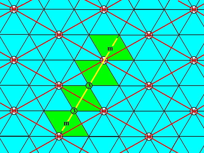
Figure 6. One of the three mirror lines (yellow) intersecting at the 3-fold rotation axes (3) of the pattern of Figure 3.
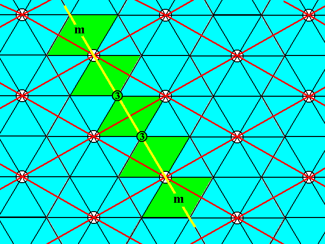
Figure 6a. A second of the three mirror lines (yellow) intersecting at the 3-fold rotation axes (3) of the pattern of Figure 3.
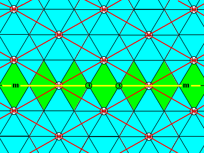
Figure 6b. A third of the three mirror lines (yellow) intersecting at the 3-fold rotation axes (3) of the pattern of Figure 3. This mirror line coincides with the longer diagonal of the unit cell.
Finally we have mirror lines coinciding with the shorter diagonal of the unit cell, as demanded by the symmetry diagram of the Plane Group P6mm :
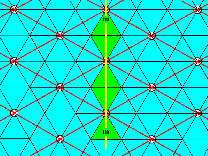
Figure 6c. Mirror lines (one indicated, yellow) coinciding with the shorter diagonal of the unit cell.
Glide lines.
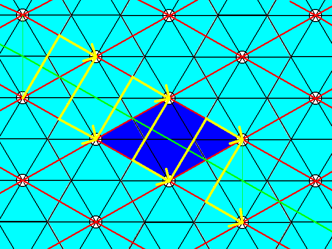
Figure 7. The pattern of Figure 3 contains glide lines connecting the centers of opposite unit cell edges. One such glide line is drawn. The unit cell is indicated by dark blue coloring.
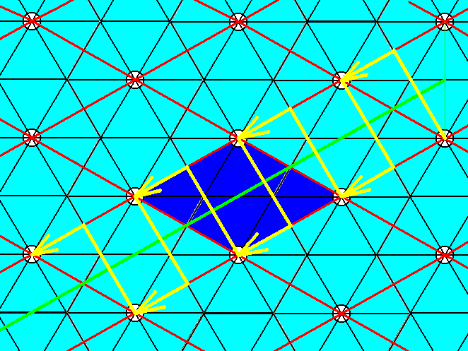
Figure 8. The pattern of Figure 3 also contains glide lines connecting the centers of the other pair of opposite unit cell edges. One such glide line is drawn. The unit cell is indicated by dark blue coloring.
The glide connecting the centers of the other pair of opposite unit cell edges, as depicted in Figure 8, is also implied by an existing mirror line.
The glide lines going through the center of the unit cells while perpendicular to two opposite edges (See symmetry diagram) are present :
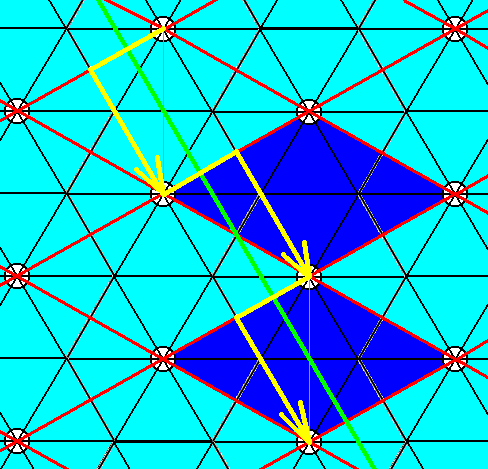
Figure 9. The pattern of Figure 3 contains glide lines perpendicular to two opposite unit cell edges while going through the cell's center. One such glide line is drawn. Two unit cells are indicated by dark blue coloring. As can be seen, the glide lines parallel to the present one, and cutting off a corner of the unit cell, are also present. Because of the mirror line coinciding with the unit cell's shorter diagonal, the other glide lines with respect to the other pair of opposite edges must also be present.
The glide lines connecting the centers of adjacent unit cell edges, and parallel to the unit cell's longer diagonal (See symmetry diagram) are present :
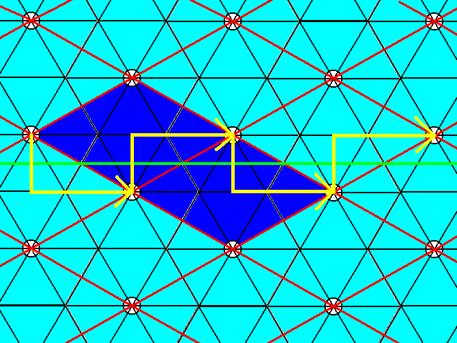
Figure 10. The pattern of Figure 3 contains glide lines connecting the centers of adjacent unit cell edges while parallel to the unit cell'a longer diagonal. One such glide line is drawn. Two unit cells are indicated by dark blue coloring.
The glide lines connecting the centers of adjacent unit cell edges and parallel to the shorter unit cell diagonal (See symmetry diagram) are also present :
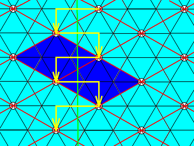
Figure 11. The pattern of Figure 3 contains glide lines connecting the centers of adjacent unit cell edges while parallel to the unit cell'a shorter diagonal. One such glide line is drawn. Two unit cells are indicated by dark blue coloring. When looking to these two unit cells we can see that the right glide line (i.e. at the right side of the unit cell) as well as the left glide line (i.e. at the left side of the unit cell) are present.
Rotation axes.
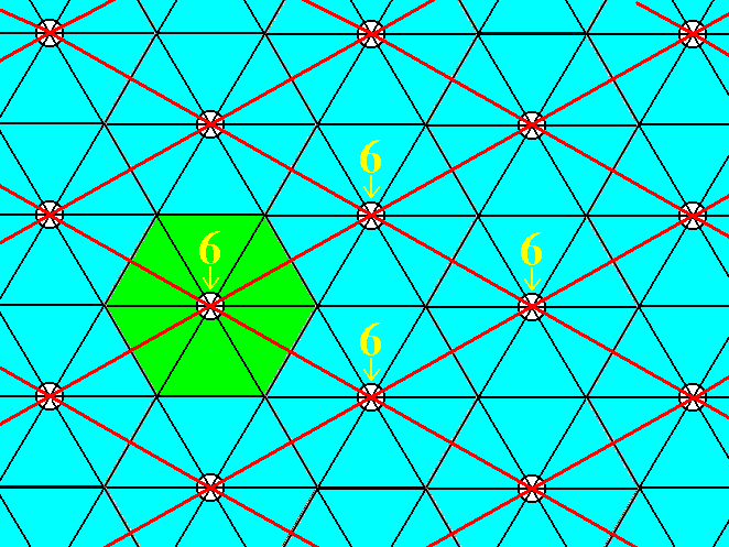
Figure 12. The pattern of Figure 3 contains a 6-fold rotation axis at each node of the hexagonal lattice, i.e. at the corners of the meshes (unit cells). Four such axes are indicated, and one of them highlighted.
The two 3-fold rotation axes in the interior of every (rhomb-shaped) unit cell (See symmetry diagram) are present :
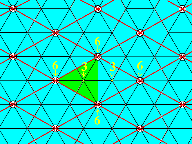
Figure 13. The pattern of Figure 3 contains two 3-fold rotation axes in the interior of the meshes of the hexagonal net. For one mesh they are indicated. One of them is highlighted.
The 2-fold rotation axes at the centers of the edges of the unit cell, and in the cell's center (See symmetry diagram), are also present :
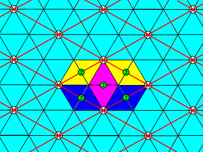
Figure 14. The pattern of Figure 3 contains a 2-fold rotation axis at the center of each unit cell edge, and one in the cell's (mesh's) center. For one mesh they are indicated and highlighted.
We have now demonstrated that the pattern of Figure 3 indeed belongs to the Plane Group P6mm. It consists of extended motifs.
The Complex Motif of this pattern is identical to the repeat unit as was given earlier, namely in Figure 2 :
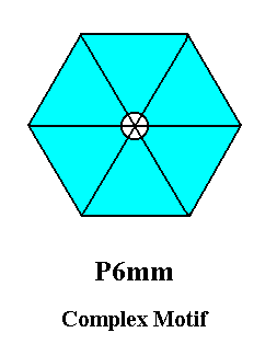
The (point) symmetry of the Complex Motif, as determined in Figure 15, is 6mm (one 6-fold rotation axis and two sets of mirror lines, each set consisting of three equivalent mirror lines).
The simplest planimetric figure expressing this symmetry geometrically is the Regular Hexagon, which was depicted in Figure 11 of the previous document.
Although we do not have to eliminate all glide translations, because parallel to each glide line there is a mirror line in the pattern of Figure 3 (See symmetry diagram), it is nevertheless instructive to do so, and see what the resulting (ultimate) Complex Motif looks like.
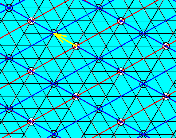
Figure 16. Elimination of the glide translation involved in the glide depicted in Figure 7. The yellow arrow indicates the shift, executed in the Copy-Shift-Superimpose operation.
To eliminate the translation involved in Figure 8, we apply the Copy-Shift-Superimpose operation (in which the shift corrresponds to the translation involved) on the just obtained result. See next Figure.
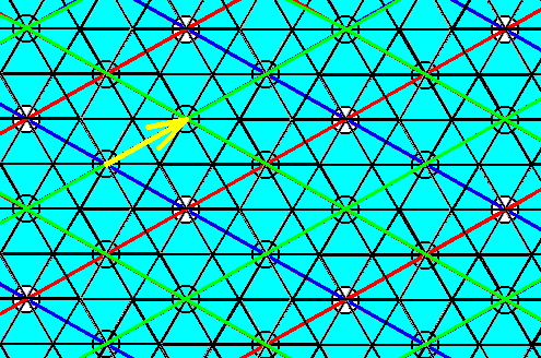
Figure 17. Elimination of the glide translation involved in the glide depicted in Figure 8. The yellow arrow indicates the shift, executed in the Copy-Shift-Superimpose operation.
With those eliminations, as executed above, all other glide translations are automatically eliminated. Let's demonstrate that.
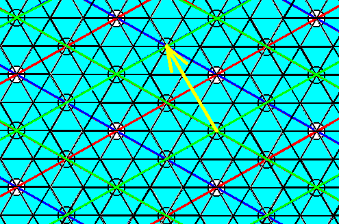
Figure 18. Elimination of the glide translation involved in the glide depicted in Figure 9. The yellow arrow indicates the shift to be executed in the Copy-Shift-Superimpose operation on the last obtained result (Depicted in Figure 17).
As we can see in Figure 18, the shift, according to the glide in Figure 9, will not bring about any further change in the pattern because it will be mapped exactly onto itself.
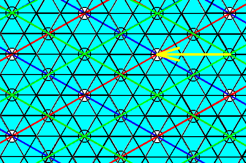
Figure 19. Elimination of the glide translation involved in the glide depicted in Figure 10. The yellow arrow indicates the shift to be executed in the Copy-Shift-Superimpose operation on the last obtained result (Depicted in Figure 17).
Also here the pattern will not change any further.
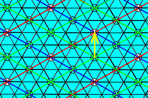
Figure 20. Elimination of the glide translation involved in the glide depicted in Figure 11. The yellow arrow indicates the shift to be executed in the Copy-Shift-Superimpose operation on the last obtained result (Depicted in Figure 17).
Again, the pattern will not change further.
So we are now sure that the pattern of Figure 17 is the final pattern that remains after all glide translations have been eliminated.
When we now isolate a repeat unit, we have automatically eliminated all simple translations, and wind up with the (ultimate) Complex Motif of the P6mm pattern of Figure 3. The next Figure indicates a repeat unit suitable to represent the Complex Motif.
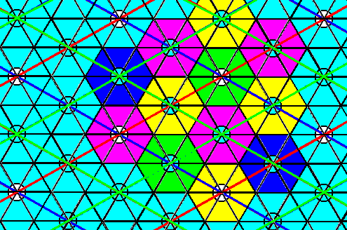
Figure 21. In the pattern that resulted after elimination of all glide translations (Figure 17), we can detect a genuine repeat unit that can serve to represent the Complex Motif of the P6mm pattern of Figure 3.
Isolating this repeat unit effects the elimination of all simple translations, and results in the Complex Motif. See next Figure.
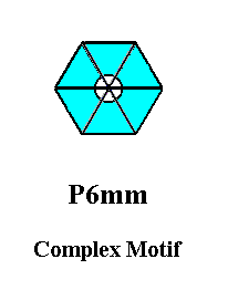
Figure 22. The (ultimate) Complex Motif of the P6mm pattern of Figure 3, obtained by elimination of all translations (glide and simple) inherent in that pattern. The resulting Complex Motif is the translation-free residue of the pattern of Figure 3.
It is perhaps instructive to compare the Complex Motifs so far obtained from P6mm patterns :
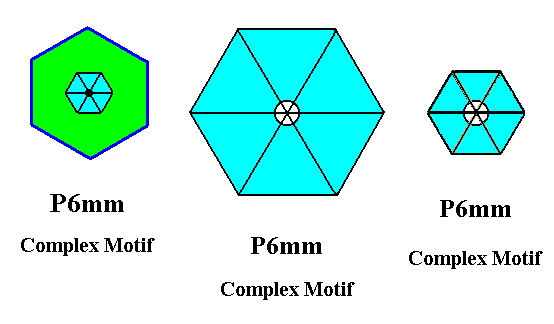
Figure 23. Comparing three Complex Motifs, so far obtained from P6mm patterns.
Left image : Complex Motif obtained from the P6mm pattern of Figure 7 of the previous document and depicted in Figure 10 of that previous document.
Central image : Complex Motif obtained from the pattern of Figure 3, without eliminating the glide translations inherent in that pattern, and depicted in Figure 15.
Right image : The (ultimate) Complex Motif of the P6mm pattern of Figure 3, obtained by elimination of all translations (glide and simple) inherent in that pattern, and depicted in Figure 22.
The first image of the above Figure involves a non-extended motif, i.e. it involves a motif s.str. plus a corresponding background. The other two images involve extended motifs. The difference between these latter Complex Motifs is that the one depicted at the right is "telescoped back", i.e. compressed : Its parts have come closer together with respect to those of the central image, in virtue of the elimination of all glide translations. Eliminations of these glide translations effects the alignment of subsystems within the pattern, thereby preserving the simple translations : There is still a repetition of units (See Figure 21). Only when such a unit is isolated the simple translations are undone, resulting in the ultimate Complex Motif of the initial pattern.
The (point) symmetry of all three Complex Motifs is 6mm (a 6-fold rotation axis and two sets of mirror lines, each set consisting of three equivalent mirror lines). The simplest planimetric figure representing this symmetry geometrically is the Regular Hexagon, which was depicted in Figure 11 of the previous document.
In the P6mm pattern of Figure 3 we had eliminated all glide translations and obtained the (ultimate) Complex Motif of that pattern. It is instructive to do the same with the P6mm pattern of Figure 7 of the previous document. Let us give that pattern once more :
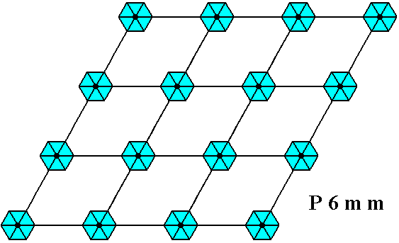
Figure 24. The P6mm pattern of Figure 7 of the previous document. It consists of non-extended motifs, i.e. of motifs s.str. plus their corresponding background.
Again we use our Copy-Shift-Superimpose operation to eliminate glide translations. For these translations (glide lines) see the symmetry diagram of the Plane Group P6mm depicted in Figure 8 of the previous document.
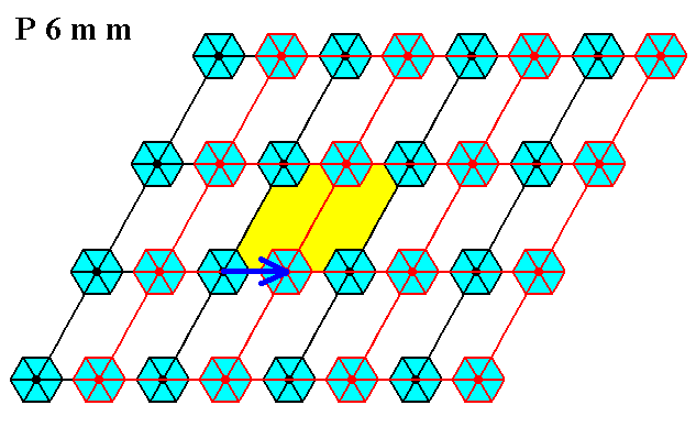
Figure 25. In the P6mm pattern of Figure 7 of the previous document the translation along half of a unit cell edge is undone by the Copy-Shift-Superimpose method.
The result will again be subjected to our operation, resulting in the elimination of the translation along half of the other unit cell edge :
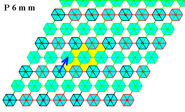
Figure 26. In the P6mm pattern of Figure 7 of the previous document the translation along half of the other unit cell edge is undone by the Copy-Shift-Superimpose method (applied to the previous result).
After some processing the result looks like this :
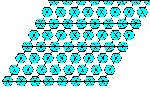
Figure 27. Final result of the elimination of the glide translations inherent in the P6mm pattern of Figure 7 of the previous document.
The next Figure shows that continuing the Copy-Shift-Superimpose operation will not bring about any further change in the pattern. So what we now have (Figure 27) is the pattern of Figure 24 in which all glide translations are eliminated.
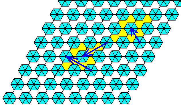
Figure 28. The pattern obtained in Figure 27 will not be further changed after continuation of the Copy-Shift-Superimpose operation.
In order to derive the (ultimate) Complex Motif of the pattern of Figure 24 in which all glide translations are eliminated, we must look for a suitable repeat unit in the glide translation-free residue (Figure 27) of that pattern. See next Figure.
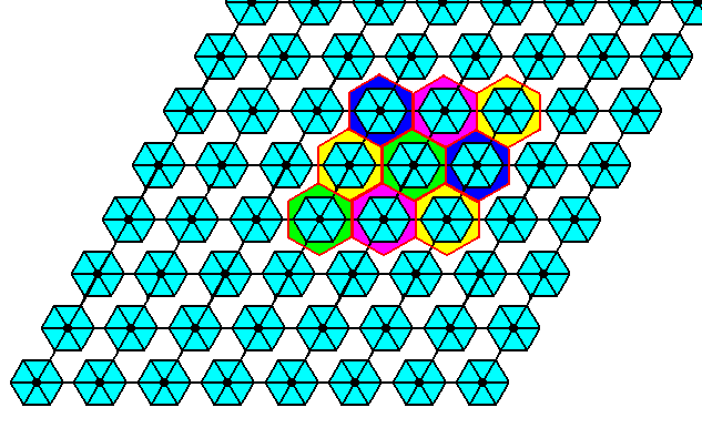
Figure 29. A suitable repeat unit to represent the Complex Motif of the P6mm pattern of Figure 24 is indicated. It tiles the plane neatly.
When we isolate such a unit we will automatically have eliminated all simple translations and obtain the Complex Motif of the pattern of Figure 24 :
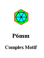
Figure 30. The Complex Motif of the P6mm pattern of Figure 24. The red line indicating the boundary of the background (green) does not belong to the Complex Motif's structure.
The next Figure compares this (ultimate) Complex Motif with the (penultimate) Complex Motif obtained earlier from the pattern of Figure 24.
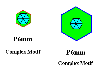
Figure 31. Ultimate and penultimate Complex Motifs of the P6mm pattern of Figure 24 compared.
Elimination of the glide translations have telescoped the background back, resulting in the ultimate Complex Motif of the P6mm pattern of Figure 24.
The (point) symmmetry of these Complex Motifs is 6mm. The simplest planimetric figure expressing this symmetry geometrically is the Regular Hexagon, which was depicted in Figure 11 of the previous document.
Having now considered the last of the 17 Plane Groups, let us summarize some results :
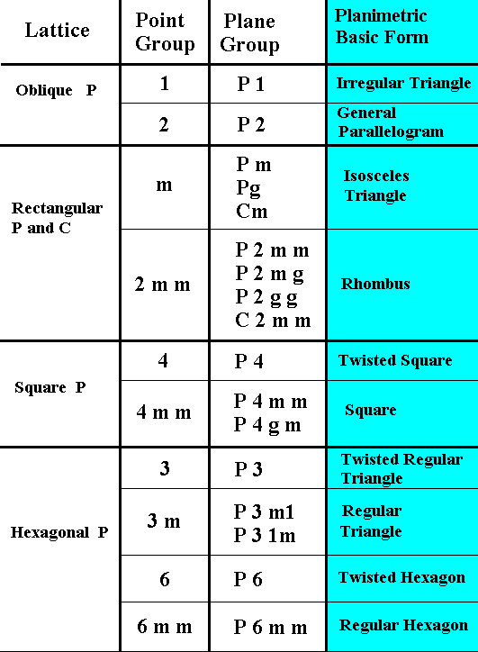
Figure 32. Lattice, Point Group, Plane Group and Promorph of 2-dimensional crystals.
The Complex Motif of crystals of a certain Class can have any shape whatsoever as long as its point symmetry complies with the Crystal Class (Point Group) of the given crystal.
If one wants to ponder more about the concepts of symmetry, and of symmetry groups, and, especially, about the much used Copy-Shift-Superimpose method for eliminating glide translations (in order to obtain the Complex Motif, and with it the promorph of the given periodic pattern), one can click HERE.
With all this we have finally c o n c l u d e d our long discussion concerning the derivation of the Complex Motif of patterns of all the 17 Plane Groups (Part I --XVII). This means that we have demonstrated that all single non-twinned (see remark further down) two-dimensional crystals have, despite their periodic nature, a t e c t o l o g i c a l a s p e c t, legitimizing a p r o m o r p h o l o g i c a l t r e a t m e n t of them. This tectological aspect expresses itself as the Complex Motif, which is the translation-free residue of the relevant two-dimensional crystal structure. The (point) symmetry of the Complex Motif determines the p r o m o r p h or planimetric basic form of the given 2-D crystal.
REMARK : A twinned 2-D crystal (i.e. an analogue of a twinned 3-D crystal) is a regular growing together of two or more crystal individuals. This automatically creates a tectology : (macroscopical) antimers (counter parts) are being formed, that directly determine the promorph of the twinned crystal.
Of course two-dimensional crystals do not exist as such in the material world (They do exist, though, in the Ideal World), but they give us much insight into the structure of three-dimensional crystals. The latter are much more complicated and diverse : while for 2-D crystals there exist only 17 Plane Groups, i.e. 17 unique types of periodic structure, for 3-D crystals there exist 230 Space Groups. One of the reasons of this proliferation is the advent of a new symmetry element in the domain of three-dimensional crystals, namely the screw axis. A scew axis is a combination of a rotation and a translation along its axis. Screw axes presuppose a 3-D space, so they cannot occur in 2-dimensional crystals.
While we treated 2-dimensional crystals exhaustively -- we considered all the 17 Plane Groups -- we will not do so with 3-D crystals. What we can say is that matters in them are analogous to the case of 2-D crystals.
In the next documents we will give some examples concerning t h r e e - d i m e n s i o n a l crystals, i.e. in what way we must visualize the C o m p l e x M o t i f emerging in 3-D crystals after elimination of all translations. Five documents will be devoted to these matters. They will be followed by three documents in which the promorph or stereometric basic form is given, indirectly based on the symmetry of the corresponding Complex Motifs, and directly based on the symmetry class (Point Group) to which the crystal belongs (The LINK just given above, concerns -- as has been said -- some more thought with respect to the elimination of glide translations, especially by our Copy-Shift-Superimpose method).
e-mail : 
To continue click HERE to prepare for the Promorphology of three-dimensional Crystals.
e-mail :

back to retrospect and continuation page
back to Internal Structure of 3-D Crystals
back to The Shapes of 3-D Crystals
back to The Thermodynamics of Crystals
back to Introduction to Promorphology
back to Anaxonia, Homaxonia, Polyaxonia
back to Protaxonia : Monaxonia
back to Stauraxonia heteropola
back to Homostaura anisopola, Heterostaura
back to Autopola oxystaura and orthostaura
back to Allopola (introduction)
back to Allopola amphipleura and zygopleura
back to the Basic Forms of Cells I
back to the Basic Forms of Cells II
back to the Basic Forms of Organs
back to the Basic Forms of Antimers
back to the Basic Forms of Metamers
back to the Basic Forms of Persons
back to the Basic Forms of Colonies
back to the first part of the Preparation to the Promorphology of Crystals
back to the second part of the Preparation to the Promorphology of Crystals
back to the third part of the Preparation to the Promorphology of Crystals
back to the fourth part of the Preparation to the Promorphology of Crystals
back to the fifth part of the Preparation to the Promorphology of Crystals
back to the sixth part of the Preparation to the Promorphology of Crystals
back to the seventh part of the Preparation to the Promorphology of Crystals
back to the eighth part of the Preparation to the Promorphology of Crystals
back to the ninth part of the Preparation to the Promorphology of Crystals
back to the tenth part of the Preparation to the Promorphology of Crystals
back to the eleventh part of the Preparation to the Promorphology of Crystals
back to the twelfth part of the Preparation to the Promorphology of Crystals
back to the thirteenth part of the Preparation to the Promorphology of Crystals
back to the fourteenth part of the Preparation to the Promorphology of Crystals
back to the fifteenth part of the Preparation to the Promorphology of Crystals
back to the sixteenth part of the Preparation to the Promorphology of Crystals