preparation
3-D Crystals
V
REMARK : When the reader feels satisfied with our established theoretical foundation (done in previous documents) that allows (single, non-twinned) Crystals to be promorphologically assessed, he or she can skip all the following, and directly proceed with The Promorphology of Crystals.
Deriving the Complex Motif of Beryl, Be3Al2(Si6O18)
Chemical bonding and Structure Control in Crystals of Silicate minerals
Before we're going to analyze the structure of Beryl crystals in order to find the Complex Motif (that lies at the base of the crystal's tectological structural aspect), something must be said with respect to chemical bonding and ionic radii in Silicates, both controlling the internal structure of their crystals (The reader should first consult the beginning of the previous document, where these matters are introduced).
In the previous document we distinguished between isodesmic, anisodesmic and mesodesmic bonding. M e s o d e s m i c b o n d i n g represents a special case where the anion-cation bond takes up exactly one-half of the available anion charge. The silicates provide the best example. Si4+ almost always coordinates with four O2- in what is known as a S i l i c o n t e t r a h e d r o n. The EVB ( = electrostatic valence bond ) strength is therefore 4/4=1, which is exactly one-half of the negative 2 charge on Oxygen. This leaves a -1 charge on each Oxygen available to bond with a second SiO4+ by sharing an Oxygen between tetrahedra. Each Silicon tetrahedron can potentially share Oxygen ions with one, two, three or four adjacent tetrahedra. The degree to which Silicon tetrahedra share Oxygen ions with adjacent tetrahedra and polymerize to form pairs, chains, rings, sheets, and three-dimensional frame works, provides the basis for classification of the Silicate minerals. The Silicates are the only common mesodesmic group. The structure of these minerals is controlled by the geometry of the anionic group and the requirement for additional cations to coordinate with the anions in the anionic groups to satisfy any remaining negative charge.
As has been said, Silicates consist of SiO4 tetrahedrons. The powerful bond that unites the Oxygen and Silicon ions is literally the cement that holds the Earth's crust together (The earth'crust is mainly composed of silicate minerals). This bond may be estimated by use of Pauling's electronegativety concept as 50% ionic and 50% covalent. That is, although the bond arises in part from the attraction of oppositely charged ions, it also involves sharing of electrons and interpenetration of the electronic superstructures of the ions involved. The bond is strongly localized in the vicinity of these shared electrons. Although electron sharing is present in the Si--O bond, the total bonding energy of Si4+ is still distributed equally among its four closest Oxygen neighbors. Hence, as has been mentioned earlier, the strength of any single Si--O bond is equal to just one-half the total bonding energy available in the Oxygen ion. Each O2- has, therefore, the potentiality of bonding to another Silicon ion and entering into another tetrahedral grouping, thus uniting the tetrahedral groups through the shared (or bridging) Oxygen : polymerization. In no case, however, are three or even two Oxygens shared between two adjacent tetrahedra in Nature. Such sharing would place two higly charged Si4+ ions close together and the repulsion between them would render the structure unstable.
The structure of Beryl
Crystals of the Silicate mineral Beryl, Be3Al2(Si6O18), have a point symmetry
6/m 2/m 2/m, and thus belongs to the Dihexagonal-bipyramidal Crystal Class of the Hexagonal System. The Space Group is P 6/m 2/c 2/c, indicating that there are two non-quivalent sets of c-glides present in the structure.
Crystals of Beryl are frequently of considerable size with rough faces. At Albany, Maine, a tapering crystal 9 meters long weighed over 25 tons.
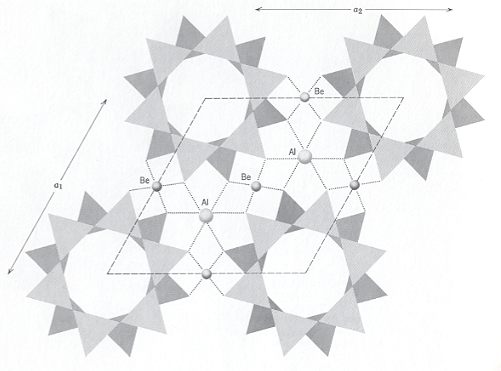
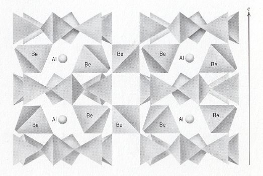
The Beryl structure consists of 6-fold rings of linked SiO4 tetrahedrons, alternated with Beryllium atoms (Be) and Aluminum atoms (Al). The tetrahedrons in the 6-fold rings are arranged so that the plane of the ring also is a plane of symmetry of the constituent tetrahedrons. Tetrahedra rings are stacked to form columns so that successive rings are rotated relative to the rings above and below. This allows the Oxygen anions from one tetrahedral ring to nestle in the low spots between Oxygen anions in the adjacent rings, i.e. the rings below and above. Each column of rings therefore consists of two concentric cylinders of Oxygen anions. These columns of rings extend parallel to the c-axis, and are stacked next to each other in a hexagonal array. Beryllium occupies distorted 4-fold sites formed by Oxygen anions from adjacent columns of rings and links the rings laterally and vertically. Aluminum occupies distorted 6-fold sites formed by Oxygen anions from three adjacent columns of rings.
The combination of tetrahedra rings and cross-linking Be tetrahedra actually forms a Framework Silicate (Tectosilicate). But because the rings are the dominant structural element, Beryl is normally grouped with the Ring Silicates (Cyclosilicates). The next Figures illustrate the structure of Beryl.
As has been said, the columns, when viewed along the c-axis, form a hexagonal array, as the next Figure shows.
If we think of the above structure (Figure 3) as indefinitely extended in space, then we see the following symmetry elements : 6-fold rotation axes going through the middle of the columns of rings, parallel to the c-axis (i.e. normal to the plane of the drawing). In every such 6-fold axis two (non-equivalent) sets of glide planes come together (They are indicated as c's in the Space Group symbol P 6/m 2/c 2/c, while the 6-fold rotation axes are indicated by 6).
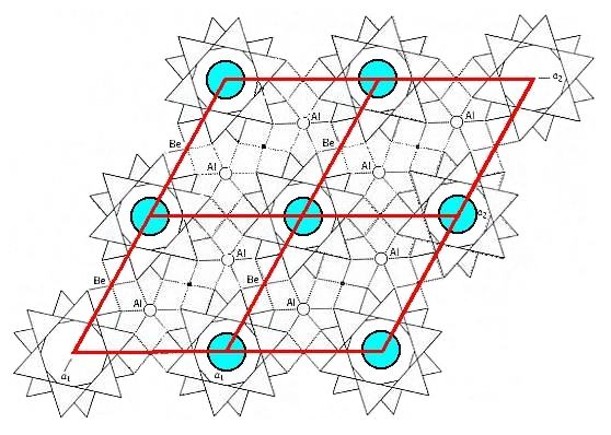
As Figure 3 indicates, there are two possible choices of unit cell, a rhombic unit cell and a hexagonal unit cell, and the latter has more (point) symmetry than the former. Because we know that crystals of Beryl crystallize in the highest symmetrical Class of the Hexagonal System (6/m 2/m 2/m) we will, in the process of finding the Complex Motif, concentrate on the content of the hexagonal unit cell. Seen in the direction of the c-axis (which is a 6-fold rotation axis) this hexagonal unit cell looks like this :
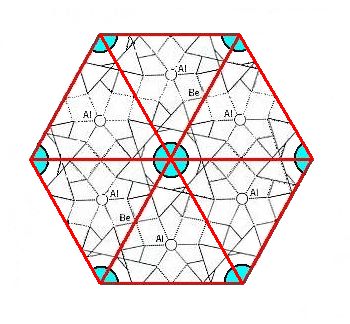
Figure 4. Top view of the hexagonal unit cell of the Beryl structure along the c-axis. The columns of rings are highlighted by blue discs. The upper layer of the unit cell consists of six-fold rings, one in the center of the layer and six one-thirds of such a ring at the cell's periphery.
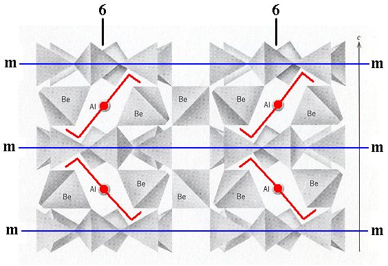
The next Figure shows the symmetry of the content of the hexagonal unit cell.
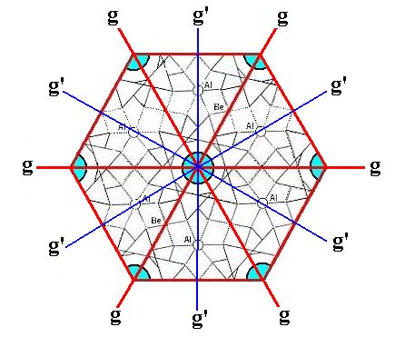
Figure 5. Top view of the hexagonal unit cell of the Beryl structure along the c-axis. The columns of rings are highlighted by blue discs. The following symmetry elements are visible :
A 6-fold rotation axis, perpendicular to the plane of the drawing and going through the center of the image. If we imagine the unit cell to be repeated indefinitely along the c-axis, then we can (after having analyzed the structure) detect two (non-equivalent) sets of glide planes, g and g'.
If we now explicitly consider only a single hexagonal unit cell (and thus eliminate all simple translations) and at the same time eliminate the translational components of the c-glides (that then turn into mirror planes), then we obtain the Complex Motif of crystals of Beryl, which has the following point symmetry : One 6-fold rotation axis running through the mid-line of the the hexagonal prism (which earlier constituted the outline of the unit cell). Two (non-equivalent) sets of mirror planes containing the 6-fold axis. Further, perpendicular to each of these mirror planes, there is a 2-fold rotation axis. And finally, we see one mirror plane coinciding with the equatorial plane of the hexagonal prism. So the point symmetry of the Complex Motif is 6/m 2/m 2/m.
On the elimination of the glide translations in the Beryl structure.
The elimination of the translational components of the c-glides goes as follows : Within the Beryl structure we can concentrate on one column of SiO4 rings, and within such a column we can distinguish two interleaved structural subsystems stacked along the c-axis. These structural subsystems differ from each other only by their orientation. They relate to each other by a glide. An important part of such a subsystem, a part that is visibly responsible for the presence of the c-glide, is constituted of SiO4 rings that are stacked (while interleaved with layers of Be + Al). The next Figure depicts one such ring.
Figure 5a. Top view of a 6-fold ring of SiO4 tetrahedra.
If we are going to reflect this ring with respect the reflection plane indicated by a red line in the next Figure,
Figure 5b. A 6-fold ring of SiO4 tetrahedra that is going to be reflected across the line (imagined as a plane normal to the plane of the drawing) indicated.
then the elements of that ring will appear on either side of the reflection plane :
Figure 5c. Reflection of a 6-fold ring of SiO4 tetrahedra across the red line (imagined as a plane normal to the plane of the drawing) as indicated.
Figure 5d. Final result of the reflection of a 6-fold ring of SiO4 tetrahedra across the line (imagined as a plane normal to the plane of the drawing) as indicated.
If we now move the reflection image of the ring (i.e. the green ring) downward along the c-axis for a certain distance, then this moved image is related to the original ring, with which we began (the blue ring), by a glide operation. The next Figure depicts this.
Figure 5e. The reflection image is translated a certain distance along the c-axis, i.e. away from the beholder. So the green ring now lies beneath the blue ring. They are now related to each other by a glide operation.
If we look just to the two rings (with one ring below the other), thus if we do not consider other elements of the Beryl structure, we see two sets of glide planes, each set consisting of six thereof. Only half of them survive when we consider the whole structure, as is evident in Figure 5, i.e. 3+3 glide planes. This set of 3+3 glide planes is present in every unit cell of the structure and thus repeated all over the Beryl structure. The next Figure shows the just mentioned 2x6 glide planes of a system (only) consisting of two rings, (the glide planes) indicated by red and dark blue lines.
Figure 5f. The system, consisting of two SiO4 rings (while not considering the elements that are interleaved between the rings), possesses two sets ( 'red' and 'dark blue' ) of g l i d e p l a n e s indicated by red and dark blue lines. Only half of them are actually present in the overall structure, and as such repeated with every unit cell of the Beryl structure.
Of course not only the rings are involved in such a reflection and translation (glide operation), but the whole structure is so involved (The whole structure possesses this symmetry, which means that when it is subjected to the operation implied by this symmetry it will remain unchanged). Considering one column of rings, we must imagine that a ring + the Be and Al atoms lying directly under that ring (See Figure 2) is being reflected and translated as indicated above. Well, the rings of a column (with their associated Be and Al atoms) represent the interleaved structural subsystems of which we spoke above : a blue system and a green system related to each other by a glide operation. Making use of Figure 2 we can indicate these subsystems as follows :
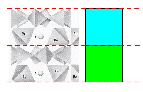
Figure 5g. The domain of the two structural subsystems (blue, green) in the Beryl structure. Two rings and two layers of Be + Al atoms are shown.
The following Figures diagrammize those subsystems. As has been said, these subsystems are related to each other by a glide operation. This means that, in addition to a reflection, a t r a n s l a t i o n is involved.
Figure 6. Diagram of the elimination of the glide translations in the Beryl structure.
Left image : Two structural subsystems, blue and green, related to each other by a glide plane. Each subsystem consists of parts. Such a part is symbolized by a square.
Middle image : The green subsystem is shifted upwards till it aligns with the blue subsystem.
Right image : The resulting structure, after doing away with the empty spaces. As is already evident in the middle image, the glide planes have been transformed into mirror planes, separating mirror images ( Recall that initially the subsystems only differed by their position and orientation with respect to each other. In all other respects they are identical, and here this means that they are symmetric images, i.e. a blue part relates symmetrically to a green part ).
The next Figure indicates the glide plane and mirror plane involved in Figure 6.
Figure 6a. The glide plane and the mirror plane involved in Figure 6.
A second method -- leading to the same result -- of eliminating the translational components of the glide planes is to make a copy of the whole structure which contains the two subsystems (related to each other by a glide plane), then shifting this copy till the parts of its subsystems align with the corresponing parts of the subsystems of the original (i.e. till each blue square of the copy comes to lie at the same level as the corresponding green square of the original), and finally superimposing the shifted copy onto the original. See next Figure.
Figure 7. Diagram of the elimination of the glide translations in the Beryl structure. From left to right :
First image : Two structural subsystems, blue and red, related to each other by a glide plane.
Second image : Copy of the first image.
Third image : Shifting the copy upwards till the blue subsystem of the copy aligns with the green subsystem of the original, i.e. till every blue part of the copy aligns with a corresponding green part of the original.
Fourth image : Superimposing the shifted copy onto the original.
Although the ring structures now become 12-fold structures, the whole (i.e. the overall) structure remains 6-fold, because -- among other things -- of the six-fold (hexagonal) distribution of those rings : See Figures 3 and 4.
Final derivation of the Complex Motif of the Beryl structure.
In the Figures 6 and 7 we have eliminated the glide translations. Now we must determine how many layers of our structure must be preserved such that the result stands for the Complex Motif (which must be a repeating unit). In the mentioned Figures we considered two structural subsystems within the Beryl structure -- indicated by coloring the parts of such a subsystem either blue or green -- that were related to each other by a glide operation. For reasons of clarity we considered each part of such a subsystem as a homogeneous unit (indicated by a homogeneously colored square). But in fact in Beryl the parts of such a subsystem are not homogeneous, but asymmetric with respect to a horizontal plane, i.e. a plane perpendicular to the c-axis. This we can see in Figure 2, and also in Figure 5f : One part of the 'blue' subsystem consists of a layer of rings + a layer of Be and Al atoms. Directly below is a part of the second subsystem, i.e. the 'green' subsystem. And that part also consists of a layer of rings + a layer of Be and Al atoms. Directly below it we encounter a part of the 'blue' subsystem again, and this part again consists of a layer of rings + a layer of Be and Al atoms, etc. So each part of such a subsystem indeed lacks a horizontal mirror plane.
In accord with all this we again eliminate the glide translations, as was diagrammed above, but now we take the mentioned asymmetry into account and see what happens :
Figure 8. Diagram of the elimination of the glide translations in the Beryl structure, according to Figure 6. The fact that each subsystem consists of non-symmetric parts is indicated by coloring one half of each part red.
After we have eliminated the glide translations we must look for the smallest repeated unit in the vertical direction, i.e. along the c-axis. See next Figure
Figure 9. Isolation of the smallest repeated unit in the vertical dimension.
1. Isolation of a segment from the result obtained in Figure 8.
2. Erasion of all auxiliary lines.
3. Because of the elimination of the glide translations, horizontally adjacent parts are symmetric with respect to a vertical mirror plane. This is symbolized by the coloring.
4. The horizontal mirror plane is explicitly indicated, as well as one vertical mirror plane (belonging to the triplet of vertical mirror planes in the point symmetry of a Beryl crystal).
So now we know that the Complex Motif consists of an upper layer of 1+6x1/3 (superimposed) rings (For "1+6x1/3", See Figure 4) (So in fact we have, in virtue of the superposition, 2x(1+6x1/3) = 6 rings), downwardly followed by a (superimposed) layer of Be and Al atoms, finally followed by again a layer of 1+6x1/3 (superimposed) rings. So its symmetry is indeed 6/m 2/m 2/m.
The simplest geometric solid to express the Complex Motif's symmetry of 6/m 2/m 2/m is the r e g u l a r H e x a g o n a l B i p y r a m i d.
Although the Hexagonal Prism also expresses this symmetry, it is idem specie divisible, i.e. divisible into parts which themselves still possess that same symmetry, and as such less preferable.
According to all this the promorph of single non-twinned crystals of Beryl belongs to the Isostaura polypleura (Stauraxonia homopola), and within these : to the Polypleura dodecapleura.
With our derivation of the Complex Motif of crystals of the mineral Beryl, we c o n c l u d e our preparation to the Promorphology of 3-dimensional crystals.
In the next document we will recapitulate some generalities and d e f i n e precisely how to consider any (single none-twinned) crystal promorphologically. This is directly followed by actually determining the promorph (= stereometric basic form) of the crystals of all the 32 Crystal Classes.
To continue click HERE to actually begin with the Promorphology of Crystals (first part).
e-mail :

back to retrospect and continuation page
back to Internal Structure of 3-D Crystals
back to The Shapes of 3-D Crystals
back to The Thermodynamics of Crystals
back to Introduction to Promorphology
back to Anaxonia, Homaxonia, Polyaxonia
back to Protaxonia : Monaxonia
back to Stauraxonia heteropola
back to Homostaura anisopola, Heterostaura
back to Autopola oxystaura and orthostaura
back to Allopola (introduction)
back to Allopola amphipleura and zygopleura
back to the Basic Forms of Cells I
back to the Basic Forms of Cells II
back to the Basic Forms of Organs
back to the Basic Forms of Antimers
back to the Basic Forms of Metamers
back to the Basic Forms of Persons
back to the Basic Forms of Colonies
back to the first part of the Preparation to the Promorphology of Crystals
back to the second part of the Preparation to the Promorphology of Crystals
back to the third part of the Preparation to the Promorphology of Crystals
back to the fourth part of the Preparation to the Promorphology of Crystals
back to the fifth part of the Preparation to the Promorphology of Crystals
back to the sixth part of the Preparation to the Promorphology of Crystals
back to the seventh part of the Preparation to the Promorphology of Crystals
back to the eighth part of the Preparation to the Promorphology of Crystals
back to the ninth part of the Preparation to the Promorphology of Crystals
back to the tenth part of the Preparation to the Promorphology of Crystals
back to the eleventh part of the Preparation to the Promorphology of Crystals
back to the twelfth part of the Preparation to the Promorphology of Crystals
back to the thirteenth part of the Preparation to the Promorphology of Crystals
back to the fourteenth part of the Preparation to the Promorphology of Crystals
back to the fifteenth part of the Preparation to the Promorphology of Crystals
back to the sixteenth part of the Preparation to the Promorphology of Crystals
back to the seveneenth part of the Preparation to the Promorphology of Crystals
back to the first part of the Preparation to the Promorphology of 3-D Crystals
back to the second part of the Preparation to the Promorphology of 3-D Crystals
back to the third part of the Preparation to the Promorphology of 3-D Crystals
back to the fourth part of the Preparation to the Promorphology of 3-D Crystals