
REMARK : When the reader feels satisfied with our established theoretical foundation (done in the previous two documents) that allows (single, non-twinned) Crystals to be promorphologically assessed, he or she can skip all the following, and directly proceed with The Promorphology of Crystals.
REMARK : When we, in the text, refer to a certain Figure, we have often done so by means of a LINK, in order to facilitate comparison.
Sequel to the Plane Group P3m1
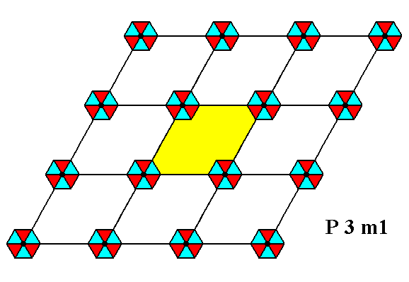
Figure 1. Periodic two-dimensional pattern according to the Plane Group P3m1. The pattern must be considered as indefinitely extended in 2-D space. A unit cell (mesh) is indicated (yellow).
In our pattern of Figure 1, representing a P3m1 periodic pattern, we were able to distinguish between a motif s.str. and the c o m p l e t e motif, i.e. the motif s.str. plus its corresponding background. Here the symmetry of the whole motif is fully determined by the symmetry of the motif s.str. So it must be possible that there exists a motif pattern in which the whole motif consists of (a larger version of) the motif s.str., which is our hexagonal tri-radiate figure, and nothing else, and which is equally well a P3m1 pattern, i.e. which has not only exactly the same total symmetry as the pattern of Figure 1, but has the same ordering so that the same net (point lattice) can underlie it. These e x t e n d e d m o t i f s, that do not leave room for background space anymore, consequently should lie on the same lattice points as was the case in Figure 1.
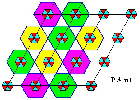
Figure 1a. Periodic two-dimensional pattern (Figure 1) according to the Plane Group P3m1. Areas of extension (around each motif s.str.) are indicated. When we extend the motifs s.str. concentrically into these areas, they cannot, while so extending, tile the plane, which means that they are not true repeat units.
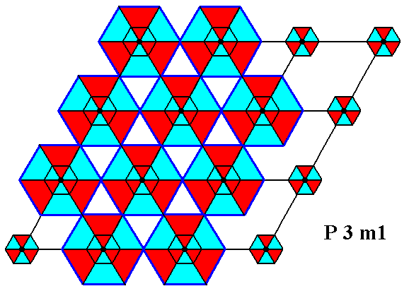
Figure 1b. Performed uniform extension of each motif s.str. (exemplified by some of them) of the P3m1 pattern of Figure 1. As extended that way they cannot tile the plane, which means that they are not true repeat units.
This was also shown in Figure 16 of Part 7 concerning the Plane Group P3.
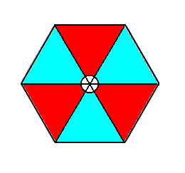
Figure 2. Arbitrarily extended motif of the pattern of Figure 1. Its (point) symmetry is 3m, which means that it possesses three equivalent mirror lines at angles 1200, and one 3-fold rotation axis. The motif consists of a circular center and six patches radiating from it in a regular way, three blue and three red.
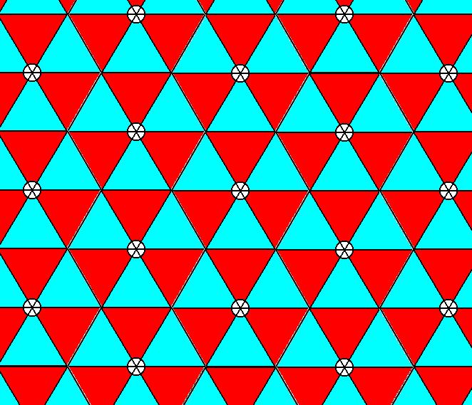
Figure 3. A pattern built up by the tiling of a plane with a hexagonally outlined space-filling tri-radiate motif (Figure 2) turns out NOT to be compatible with the Plane Group P3m1. It has been transformed into a pattern whose total symmetry is the same, it is true, but whose symmetry distribution is according to Plane Group P31m (instead of P3m1). So it has become a different pattern.
The next Figure indicates that indeed the pattern of Figure 3 consists of a repetition of the extended motif as is given in Figure 2.
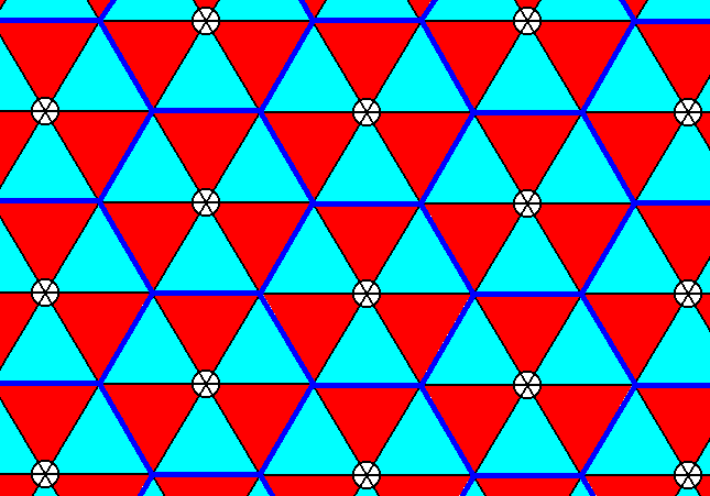
Figure 3a. The boundaries of the hexagonal tiles (extended motifs), constructing the pattern of the previous Figure, are indicated.
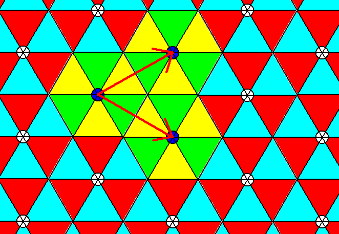
Figure 4. The same pattern as in Figure 3 (and 3a).
Three extended motifs are highlighted to show how they build up the structure. The extended motifs do not overlap. The stacking directions are indicated by the arrows.
As one can see, the s t a c k i n g d i r e c t i o n s in the pattern of Figure 3 (and indicated in Figure 4) are different from those in the pattern of Figure 1. They differ by 300.
We will show that the pattern as obtained in Figure 3 is a P31m pattern and not a P3m1 pattern.
In analyzing the structure of Figure 3, and demonstrating that it belongs to the Plane Group P31m, we will let the orientation of the motifs be the same as it was WITH RESPECT TO THE DRAWING AREA, and draw a corresponding n e w hexagonal net (point lattice), which indicates the configuration of symmetry elements in the pattern. In order to create the appropriate net, which will be compatible with Plane Group P31m, we CANNOT simply rotate the initial net by 300. The difference between the two Plane Groups P3m1 and P31m is a rotation of each m o t i f s. str. about its symmetry axis, while its background is not rotated with them, and this is NOT equivalent to a corresponding rotation of the initial n e t.
We will now demonstrate that all the symmetry ingredients and their distribution of Plane Group P31m are present in the pattern of Figure 3.
These ingredients and their distribution are given in the next Figure (symmetry diagram).
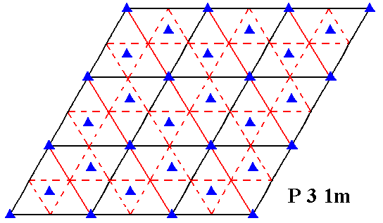
Figure 5. Symmetry content of 2-D patterns according to the Plane Group P31m. Glide lines are indicated by dashed lines. Mirror lines are indicated by red and by black solid lines, while the 3-fold rotation axes are indicated by small triangles.
First we determine the appropriate point lattice (net) for the structure of Figure 3 :
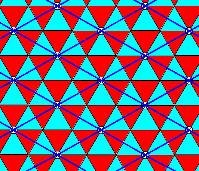
Figure 6. An appropriate net is added to the pattern of Figure 3. The unit cell is a rhombus with angles of 600 and 1200.
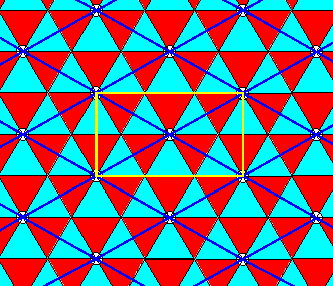
Figure 6a. In the pattern of Figure 6 we can recognize a centered rectangle. But the structure is not compatible with a centered rectangular net, because the angle of the diagonals of the rectangle of a centered rectangular net is not fixed : The cosine of the greater angle obtained by the diagonals is equal to a / 2b, in which a is the shorter side of the rectangle, while b is its longer side. The values in the hexagonal net on the other hand, are fixed : 1200 and 600, so they are special.
In Figure 6 we can easily recognize the 3-fold rotation axes of the Plane Group P31m at their proper places. Also the mirror lines coinciding with the edges of the rhomb-shaped unit cell are evident, as well as the mirror line coinciding with the shorter diagonal of that unit cell.
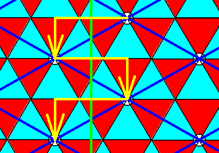
Figure 7. Demonstration of the glide lines (exemplified by one of them) parallel to, but not coincident with, the shorter diagonal of the rhomb-shaped unit cell of the pattern of Figure 3.
The next two Figures show that also the glide lines connecting the centers of two opposite edges of the unit cell are present.
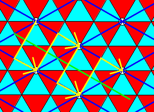
Figure 8. Demonstration of the glide lines (exemplified by one of them) connecting the centers of two opposite edges of the rhomb-shaped unit cell of the pattern of Figure 3.
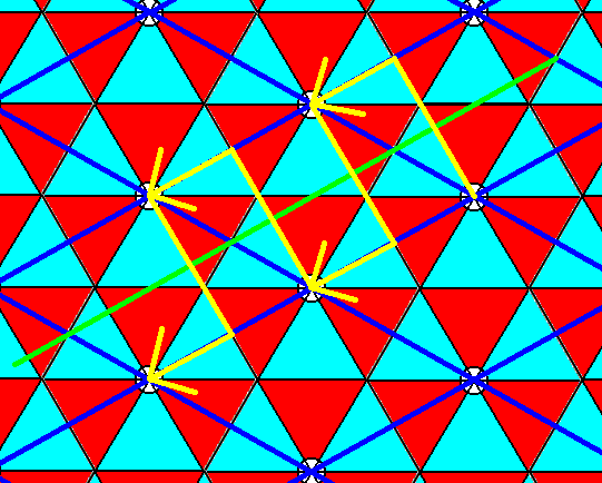
Figure 9. Demonstration of the glide lines (exemplified by one of them) connecting the centers of the two other opposite edges of the rhomb-shaped unit cell of the pattern of Figure 3.
We have now demonstrated that the pattern of Figure 3 belongs to the Plane Group P31m (and not to the Plane Group P3m1). That the P3m1 pattern cannot be obtained by just rotating the point lattice describing the repetition in the P31m pattern, is shown in the following Figure. The net of Figure 6 was rotated anticlockwise by 300, and then superimposed onto te pattern of Figure 3 :
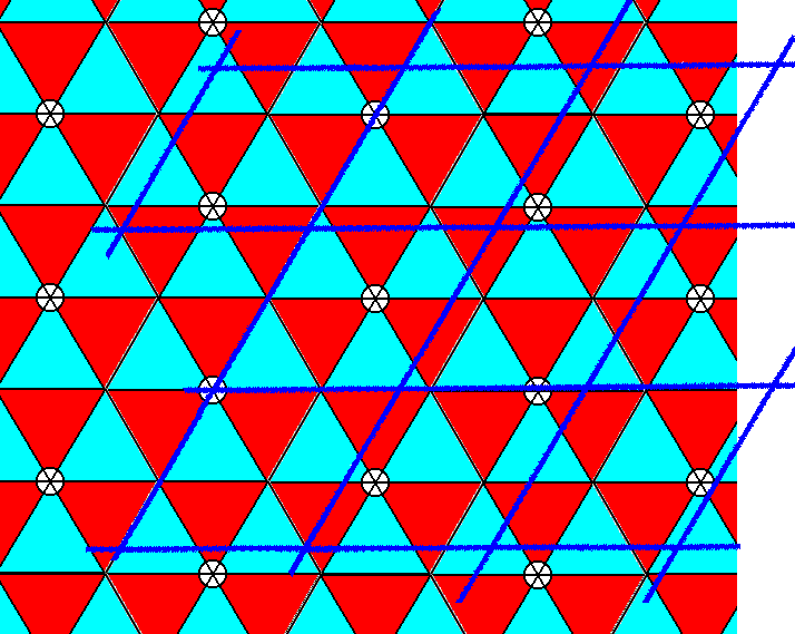
Figure 10. The net (point lattice), associated with the pattern depicted in Figure 3 and 6, was rotated anticlockwise by 300, and then superimposed onto the pattern of Figure 3. As was to be expected, the rotated net is not compatible with the pattern, showing that the Plane Group P3m1 cannot just like that be obtained by simply rotating the net describing a P31m pattern.
Also adapting the lengths of the line segments will not do, because no true unit cell is outlined, as the next Figure shows.
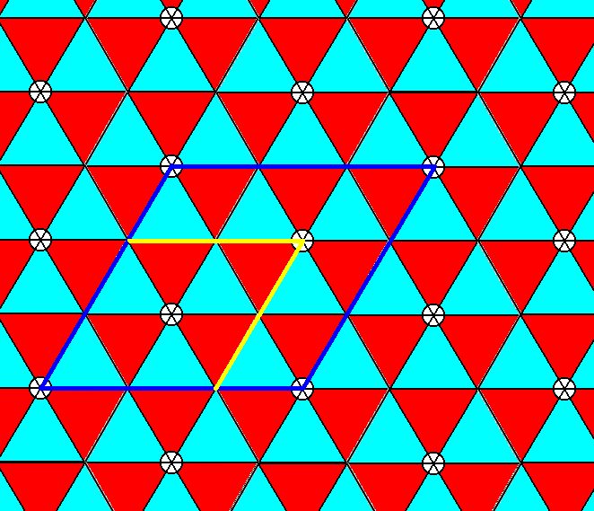
Figure 11. Adapting the dimensions of the superimposed net of Figure 10 does not yield a P3m1 pattern. Two alternative cells are shown, neither of which is a true unit cell : The smaller one consists of non-equivalent points, while the larger one contains equivalent points in its interior (resulting in a non-unique point lattice type).
We can now return to our original problem, how to e x t e n d the motifs. s.str. as they are in Figure 1, such that they fill space completely. We now know they cannot do so by just coming together and interlock among themselves (involving a reshuffling of the motifs), because then the space between them (WHICH ALSO BELONGS TO THE PATTERN) is deformed (because of the reshuffling mentioned), transforming the P3m1 pattern into a P31m pattern (See Figure 4). The only thing we can do is to let the motifs s.str. o v e r l a p and so give in to the demand of not deforming space. Figure 1a indicates how the overlap should take place : The extra spaces must be filled up.
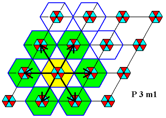
Figure 11a. The extension of one motif s.str. is indicated by the arrows. One can see that overlap takes place.
The next Figure shows the result of the extension of the one motif, as indicated in the previous Figure.
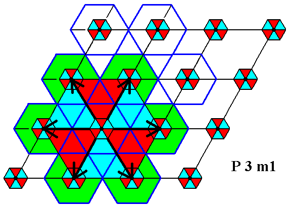
Figure 11b. The extension of one motif s.str., as indicated in the previous Figure, is carried out.
The black center in each original (i.e. not yet extended) motif s.str. is interpreted as belonging to that motif, and it should be extended too, resulting (as we set it) in the centra as we see them in the ensuing Figures.
Precisely the same as was done in the two previous Figures, must be done with the remaining motifs. When we do this we get the following pattern (drawn at slighly smaller scale) :
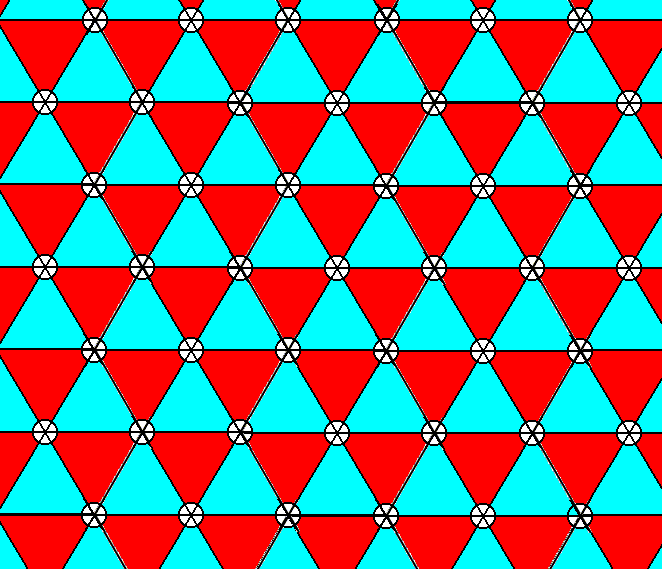
Figure 12. Space-filling of the tri-radiate motif according to the above considerations (motif extension) results in a periodic pattern according to the Hexagonal Point Lattice. The total symmetry and its distribution (configuration) of the pattern is that of Plane Group P3m1.
The next Figures indicate to what extend overlap (and thus the possession of common parts) has taken place. The extended motifs overlap in all six hexagonal directions.
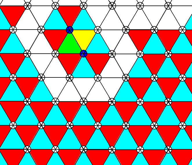
Figure 13. Pattern of Figure 12. Overlap of extended motifs in the oblique direction. Green and yellow indicate common parts.
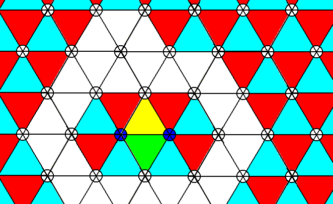
Figure 14. Pattern of Figure 12. Overlap of extended motifs in the horizontal direction. Green and yellow indicate common parts. All six hexagonal directions are equivalent, so in all these direction the described overlap (possession of common parts) is present.
The next Figure highlights four motifs associated with the four corners of the rhomb-shaped unit cell. Yellow and green indicate common parts (i.e. parts of the extended motifs commonly possessed).
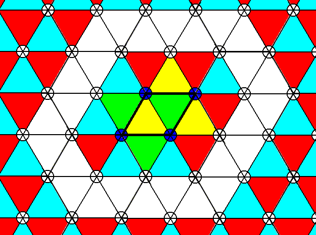
Figure 15. Pattern of Figure 12. Repeat + overlap of extended motifs in the two translation directions (as given by the edges (black) of the rhomb-shaped unit cell). The four darkened centra of four motifs indicate the corners of the rhomb-shaped unit cell. The areas of overlap are given by a green and yellow color.
The next Figures demonstrate that the pattern obtained in Figure 12 has a total symmetry and distribution according to Plane Group P3m1.
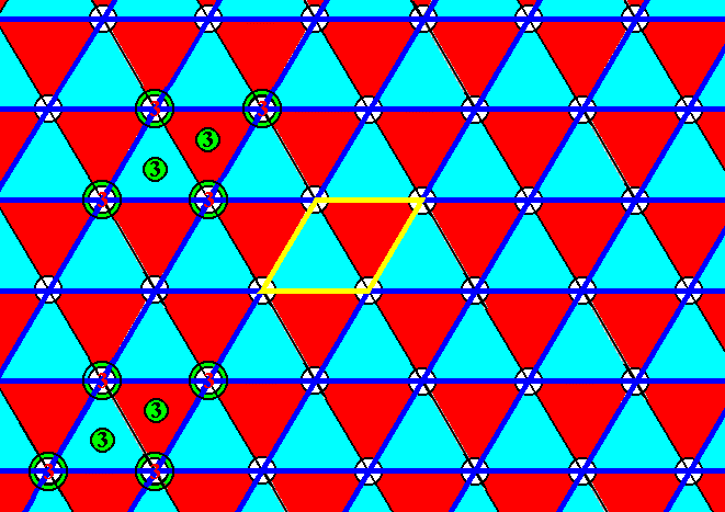
Figure 16. Pattern of Figure 12. A rhomb-shaped unit cell is highlighted (yellow). The hexagonal net, based on this unit cell, is indicated (dark blue). The symmetry of the unit cell complies with Plane Group P3m1. Some (of the many) 3-fold rotation axes are indicated ( 3 ) : They reside at the corners of each unit cell (mesh of the net), and, in addition to that, two of them are located in the interior of each unit cell.
First we give the symmetry content diagram of the Plane Group P3m1 in which all symmetry elements are indicated.
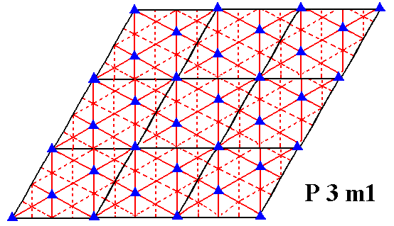
Figure 17. Symmetry content of the Plane Group P3m1. Glide lines are indicated by dashed lines. Mirror lines are indicated by red solid lines, and the 3-fold rotation axes by small triangles.
From Figure 16 it is obvious that the pattern contains 3-fold rotation axes at the corners of the rhomb-shaped unit cell and two in its interior, and has mirror lines (not shown, but easily detectable) at the proper locations.
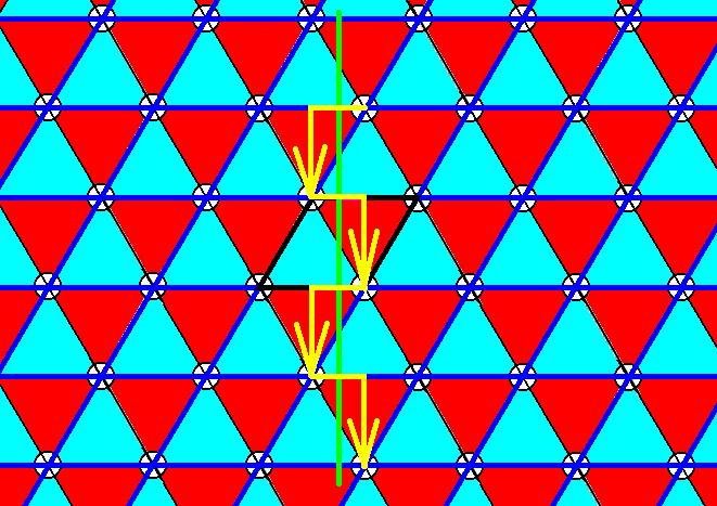
Figure 18. Pattern of Figure 12. The vertical glide line is indicated.
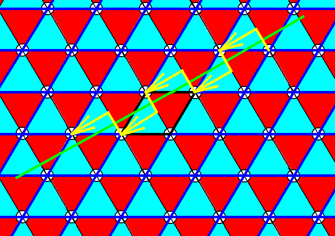
Figure 19. Pattern of Figure 12. The SW-NE glide line (See Figure 17) is indicated.
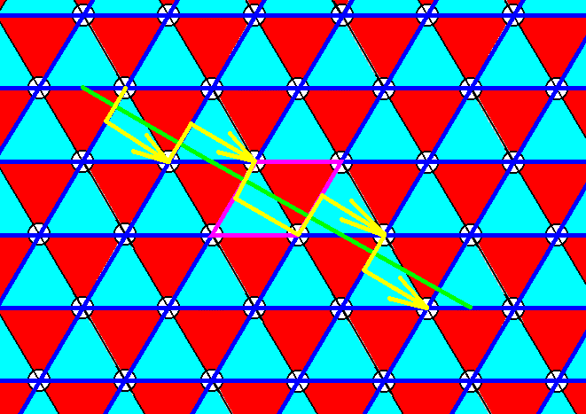
Figure 20. Pattern of Figure 12. The NW-SE glide line (See Figure 17) is indicated.
Indeed our pattern of Figure 16 complies with the Plane Group P3m1.
Analogous to the case of the Plane Group P31m as represented in Figure 6, the pattern of Figure 16 cannot be transformed into a pattern whose total symmetry is according to the Plane Group P31m by simply rotating the net by 300, as the next Figure shows.
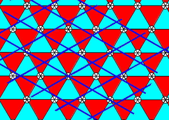
Figure 21. After having the net of Figure 16 rotated clockwise by 300, it was superimposed onto the pattern of Figure 12. It is clear that the rotated net is not compatible with the motif pattern, as was to be expected.
So we can now state that if we extend the motifs of the P3m1 pattern of Figure 1 as was done above, i.e. extend and reshuffle them till they tile the plane (Figure 3), we get the Plane Group P31m. If, on the other hand, we extend the motifs such that they become overlapped (Figure 15) and are not reshuffled, we see that they fill the plane neatly and their arrangement turns out to be according to Plane Group P3m1. The pattern, so obtained, suggests a third way of extending motifs : If we extend the motifs without letting them overlap, but extend them in such a way that their hexagonal outline (but only their outline) is turned by 300 with respect to the orientation of the initial hexagonal motif s.str., then the motifs, so extended, neatly tile the plane, they are genuine repeat units forming a periodic P3m1 pattern (now with extended motifs). See the next two Figures.
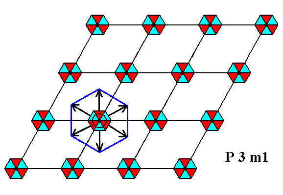
Figure 22. Indication of the third mode of motif extension in the P3m1 pattern of Figure 1, a pattern with motifs s.str. plus background. The motifs s.str. (illustrated by one such motif) take over the background in the way indicated.
The result of the extension is given in the next Figure.
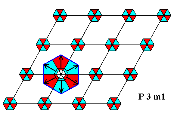
Figure 23. Result of the above described motif extension (illustrated by one such motif).
The motifs, so extended tile the plane, as the next Figure shows (The net of this next Figure is drawn at a slightly different scale, but this is immaterial for the present discussion).
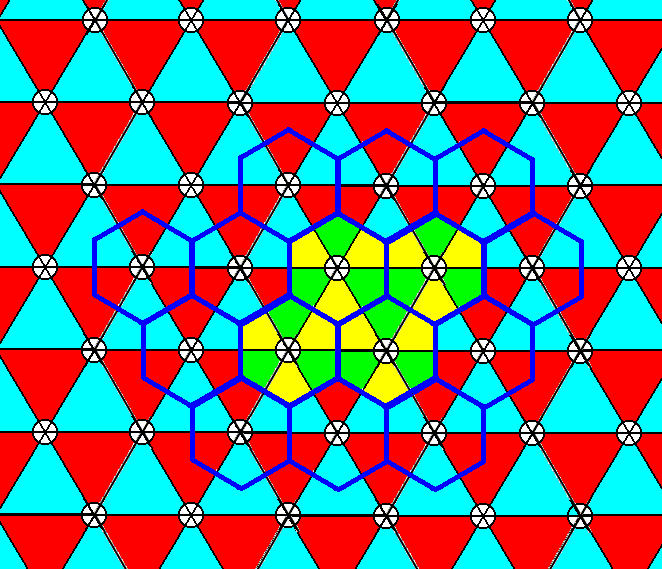
Figure 24. When we, in Figure 1 extend the motifs, as indicated in the two previous Figures and in the present Figure, they will tile the plane and form a periodic pattern according to Plane Group P3m1. Four such extended motifs are highlighted.
The extended motifs repeat according to the hexagonal net as indicated in Figure 16. See next Figure.
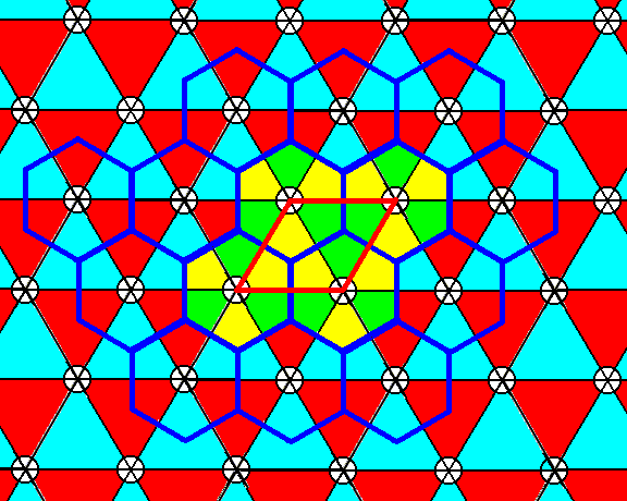
Figure 25. The extended motifs of the pattern of Figure 24 repeat according to a hexagonal net. A rhomb-shaped unit cell is indicated.
So the just determined e x t e n d e d motif is the only type of e x t e n d e d m o t i f that can represent the Complex Motif of such a P3m1 pattern with extended motifs (The other types of extended motifs either lead to a different Plane Group, or involve overlap).
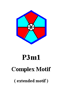
The symmetry of the Complex Motif of Figure 26 is 3m, i.e. it has one 3-fold rotation axis and three equivalent mirror lines at 1200 to each other. The latter are depicted in the next Figure.
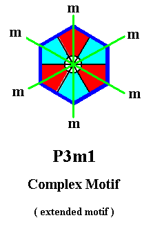
The simplest planimetric figure expressing this symmetry geometrically is the Equilateral Triangle, which as such is the promorph or planimetric basic form of all 2-D crystals belonging to the Plane Group P3m1, and with it to the Crystal Class 3m. The Equilateral Triangle was already depicted earlier (Part 8, Figure 18).
It is instructive to compare this Complex Motif, derived from the P3m1 pattern with extended motifs (as it is depicted in Figure 12), with the Complex Motif derived from the P3m1 pattern with non-extended motifs as depicted in Figure 1, as was done (i.e. derived) in the previous document, Figure 6b :
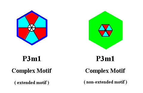
The Complex Motif of the left image of the above Figure is derived from the pattern of Figure 12, while that of the right image is derived from the pattern of Figure 1. Because the respective nets underlying those patterns differ slightly in scale, the images of the Complex motif of the above Figure differ correspondingly slightly in size. This is of course immaterial for our discussion.
In Figure 28 it is evident that the motif s.str. as is depicted in the right image, has, in the left image, invaded the whole background, resulting in a pattern fully equivalent to that of Figure 12.
The patterns with extended motifs are, in a way, the most realistic, because the chemical motifs (as we see it in 3-D crystals), are contiguous. A non-extended motif can be interpreted as some definite structure determining the symmetry of the whole motif ( = motif s.str. + corresponding background ) surrounded by a more or less structureless region, that chemically nevertheless belongs to the motif.
Of course the P3m1 Plane Group is compatible with many motifs, as long as they possess a 3m symmetry and are oriented and arranged like the motifs we discussed above (as in Figure 1 and in Figure 12).
To continue click HERE to further investigate the Plane Group P3m1.
e-mail :

back to retrospect and continuation page
back to Internal Structure of 3-D Crystals
back to The Shapes of 3-D Crystals
back to The Thermodynamics of Crystals
back to Introduction to Promorphology
back to Anaxonia, Homaxonia, Polyaxonia
back to Protaxonia : Monaxonia
back to Stauraxonia heteropola
back to Homostaura anisopola, Heterostaura
back to Autopola oxystaura and orthostaura
back to Allopola (introduction)
back to Allopola amphipleura and zygopleura
back to the Basic Forms of Cells I
back to the Basic Forms of Cells II
back to the Basic Forms of Organs
back to the Basic Forms of Antimers
back to the Basic Forms of Metamers
back to the Basic Forms of Persons
back to the Basic Forms of Colonies
back to the first part of the Preparation to the Promorphology of Crystals
back to the second part of the Preparation to the Promorphology of Crystals
back to the third part of the Preparation to the Promorphology of Crystals
back to the fourth part of the Preparation to the Promorphology of Crystals
back to the fifth part of the Preparation to the Promorphology of Crystals
back to the sixth part of the Preparation to the Promorphology of Crystals
back to the seventh part of the Preparation to the Promorphology of Crystals
back to the eighth part of the Preparation to the Promorphology of Crystals