We continue our investigation concerning the generation of group elements of the Plane Groups.
The Plane Group P6
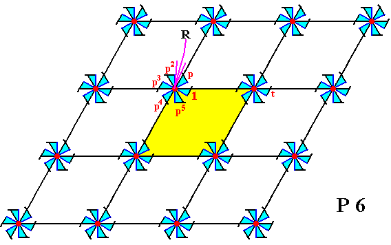
Figure 1. Inserting composed motifs, possessing point symmetry 6 , into a 2-D hexagonal point lattice, yields a periodic pattern representing Plane Group P6 .
Also here the unit mesh (yellow) is rhomb-shaped with angles of 600 and 1200.
Each motif consists of six motif units. Each motif unit is in itself asymmetric and thus can represent a group element (wherever that unit occurs in the pattern). The point R (indicated by the arrow) is the location of a 6-fold rotation axis in the pattern (there are more such axes).
The motif unit labelled 1 is chosen as the initial motif unit and as such represents the identity element of the group.
The motif unit labelled p is generated when the initial motif unit is subjected to an anticlockwise rotation of 600 about the point R . This motif unit, being a transformation, is chosen as one of the two generators of the group.
The motif unit p2 represents an anticlockwise rotation of 1200 about the point R .
The motif unit p3 represents an anticlockwise rotation of 1800 about the point R .
The motif unit p4 represents an anticlockwise rotation of 2400 about the point R .
The motif unit p5 represents an anticlockwise rotation of 3000 about the point R .
The motif unit p6 represents an anticlockwise rotation of 3600 about the point R , which is equivalent to a rotation of 00. The latter implies p6 = 1.
The motif unit labelled t represents a translation, and is chosen as the second generator.
The group P6 can be generated by the two chosen generators, p and t , i.e. they can (by combining) generate all remaining group elements, and with them all motif units that represent them.
The pattern must be conceived as indefinitely extended in 2-D space.
The next Diagram depicts the total symmetry content of the Plane Group P6.
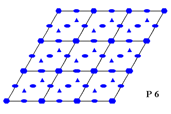
Figure 2. Total symmetry content of the Plane Group P6 .
A small solid ellipse indicates the position of a 2-fold rotation axis.
A small solid triangle indicates the position of a 3-fold rotation axis.
A small solid hexagon indicates the position of a 6-fold rotation axis.
The next Figure again gives the P6 pattern, and demonstrates the six-fold symmetry at the point R (as indicated in Figure 1).
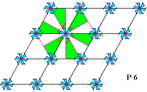
Figure 3. Six-fold symmetry of the infinite P6 pattern at the point R (There are of course many such points in the pattern).
The motif unit denoted 1 is chosen as initial motif unit, representing the identity element of the group.
The motif unit denoted p is chosen as one of the two generators of the group. The other generator is chosen to be the translation t .
The transformation p generates (from the element 1 ) the elements p , p2 , p3 , p4 and p5 . And p6 = 1.
The next Figure shows how some group elements -- represented by motif units -- are generated from the elements together representing the initial composed motif. In that composed motif the elements p2 , p3 , p4 , and p5 are produced by the generator p . And from these elements we can generate a second composed motif to the right of it, by subjecting them to the second generator of the group, the translation t . From this new composed motif we can produce yet another new composed motif by subjecting its motif units to the element p , which is an anticlockwise rotation of 600 about the point R (as indicated in Figure 1). The resulting composed motif we can see as the second one in the first row of composed motifs (See next Figure). And from this lastly obtained composed motif we can produce the other composed motifs in that first row by applying translations :
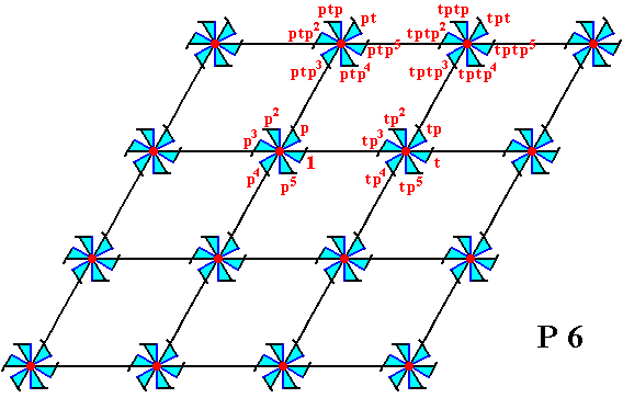
Figure 4. Generation of several composed motifs from the initial composed motif.
From the third composed motif in the second row we can produce the fourth composed motif in that same row by applying the translation t , and from this new composed motif in turn we can produce a composed motif in the fourth row (the second one in that row) by applying the transformation p4 , which is an anticlockwise rotation of 2400 about the point R (as indicated in Figure 1). This fourth row can then be completed by applying translations.
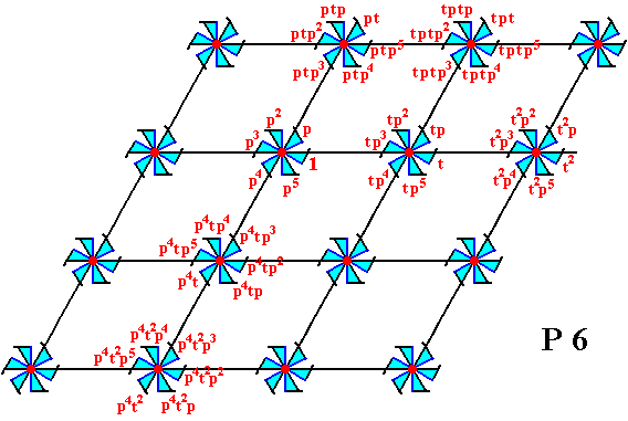
Figure 5. Generation of two more composed motifs (in addition to one obtained by a translation) of the pattern according to the Plane Group P6.
We will now generate the group elements of the group P6 again, but now letting them be represented not only by a motif unit of the motif s.str., but by such a unit PLUS its corresponding background. So the group elements will be represented by maximal areas of the pattern which are equally sized and shaped (but not necessarily equally oriented), and which tile the plane without any gaps or overlappings. In order to determine such areas we first determine a suitable choice of motif s.l.. Such motifs s.l. will then be partitioned into six areas representing group elements.
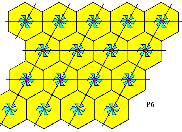
Figure 6. Motifs s.l. (yellow hexagons) of the P6 pattern of Figure 1. Each motif s.l. consists of one motif s.str. PLUS corresponding background. Partition of such motifs s.l. will yield areas that can represent group elements.
The next Figure shows the partition of the motifs s.l. into equally sized and shaped areas that can represent group elements of our P6 pattern.
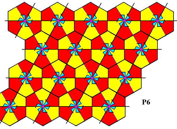
Figure 7. The motifs s.l. are each divided into six areas (bi-isosceles red and yellow triangles). Each such area can represent a group element. It consists of one basic unit of the motif s.str. (or at least it represents it) PLUS corresponding background. The colors red and yellow, in the partitioned motifs s.l. do not necessarily signify difference in symmetry. So at the center of each motif s.l. there is a six-fold rotation axis (and not just a three-fold rotation axis).
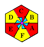
Figure 8. One partitioned motif s.l. isolated. The areas A, B, C, D, E, F represent group elements. They are situated around a six-fold rotation axis.
The next Figure indicates the areas that represent the initial element (identity element) and the two generators.
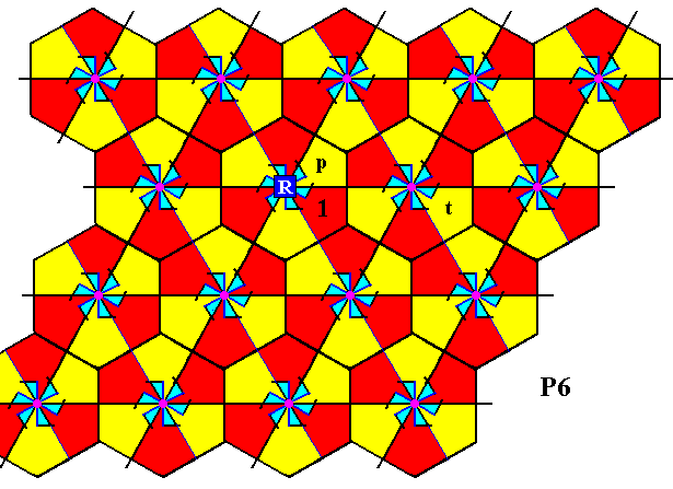
Figure 9. The P6 pattern of Figure 1 is partitioned into areas representing group elements (as it was already in Figure 7). Three such group elements are explicitly indicated :
The initial group element 1 (identity element of the group).
The generator element p , which is an anticlockwise rotation of 600 about the point R .
The generator element t , which is a horizontal translation.
By repeatedly applying the generator p to the initial element, we can generate the elements p2, p3, p4, and p5 (p6 = 1). See next Figure.
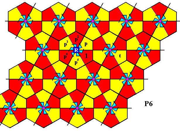
Figure 10. By applying repeatedly the generator p to the initial element, i.e. rotating the latter anticlockwise through angles of 1200 (=2x600), 1800, 2400 and 3000 about the point R , yields the group elements p2, p3, p4, p5 .
When we now subject all the group elements that are situated around the point R to translations (t-1, t, t2, t3, etc.), we will obtain all group elements of the second row of motifs s.l. :
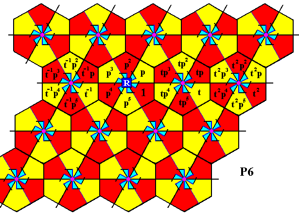
Figure 11. Completion of the filling-in of the second row of motifs s.l. of the present P6 pattern.
The next Figure indicates how we can reach the first and third rows of motifs s.l., namely the first row by the transformation p , which is an anticlockwise rotation of 600 about the point R , and the second row by the transformation p5 , which is an anticlockwise rotation of 3000 about the point R .
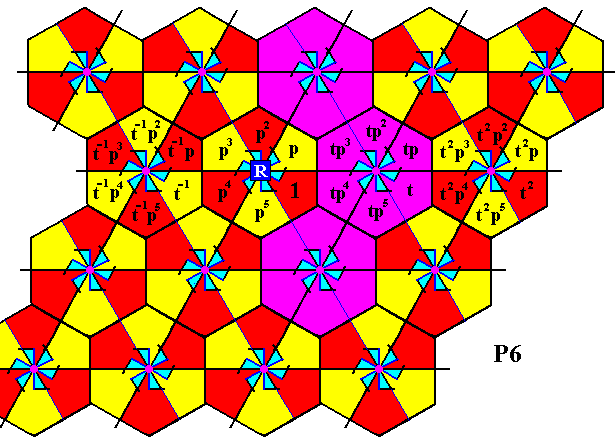
Figure 12. Two rotations can bring us to the first and third rows of the P6 pattern. See next Figure.
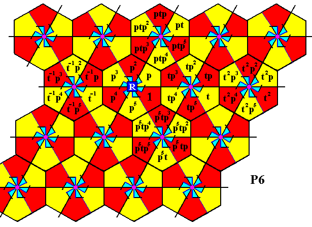
Figure 13. The first and third rows have been reached. For two motifs s.l. the group elements are generated.
These rows can now be completed by means of translations :

Figure 14. The first and third rows are completed.
The next Figure indicates how the fourth row can be reached by applying an anticlockwise rotation of 3000 of the elements of the last motif s.l. of the second row, about the point R , which means applying the transformation p5 .
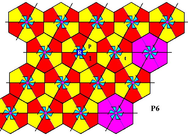
Figure 15. Indication how to reach the fourth row of the P6 pattern.

Figure 16. The fourth row has been reached, and the corresponding group elements generated.
This row can now be completed by means of translations :
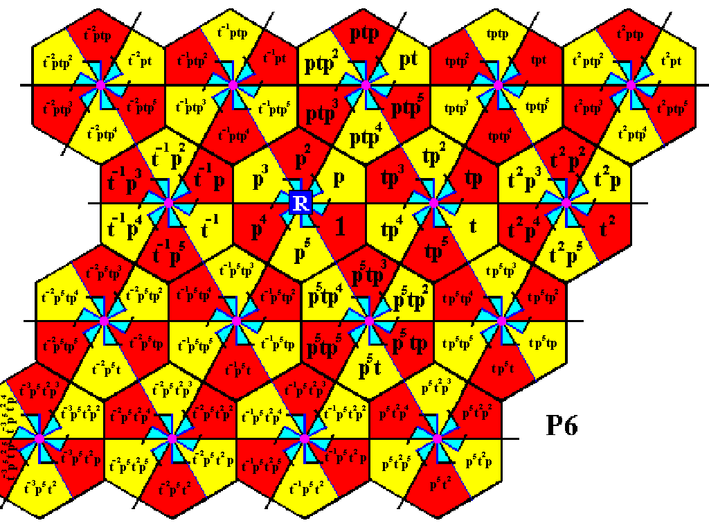
Figure 17. The fourth row of the P6 pattern is now completed.
We have now generated all group elements of the displayed part of our P6 pattern. Because the group is infinite the process should go on indefinitely.
In the next document we will generate the group elements of the last of the 17 Plane Groups, namely the group P6mm .
e-mail : 
To continue click HERE for further study of the totally dynamic and holistic nature of Reality.
back to homepage
back to the Ink-in-Glycerine Model
back to Part I of The Crystallization process and the Implicate Order
back to Part II of The Crystallization process and the Implicate Order
back to Part III of The Crystallization process and the Implicate Order
back to Part IV of The Crystallization process and the Implicate Order
back to Part V of The Crystallization process and the Implicate Order
back to Part VI of The Crystallization process and the Implicate Order
back to Part VII of The Crystallization process and the Implicate Order
back to Part VIII of The Crystallization process and the Implicate Order
back to Part IX of The Crystallization process and the Implicate Order
back to Part X of The Crystallization process and the Implicate Order
back to Part XI of The Crystallization process and the Implicate Order
back to Part XII of The Crystallization process and the Implicate Order
back to Part XIII of The Crystallization process and the Implicate Order
back to Part XIV of The Crystallization process and the Implicate Order
back to Part XV of The Crystallization process and the Implicate Order