We will now investigate the generation of the Plane Group P4gm, i.e. the generation of its group elements.
The Plane Group P4gm
Apart from the motifs considered in the previous document (Plane Group P4mm), there are still several other motifs (having different symmetries) that can be accommodated in a Square Net. These motifs have lower symmetry than the one discussed earlier. The resulting periodic pattern expresses the motif's lower symmetry.
One of these periodic patterns is especially instructive for a general understanding of two-dimensional periodic arrays. i.e. for an understanding of two-dimensional crystals, and with it an understanding of three-dimensional crystals. It is the Plane group P4gm. So we will dwell a little longer upon one of the patterns representing this Plane Group.
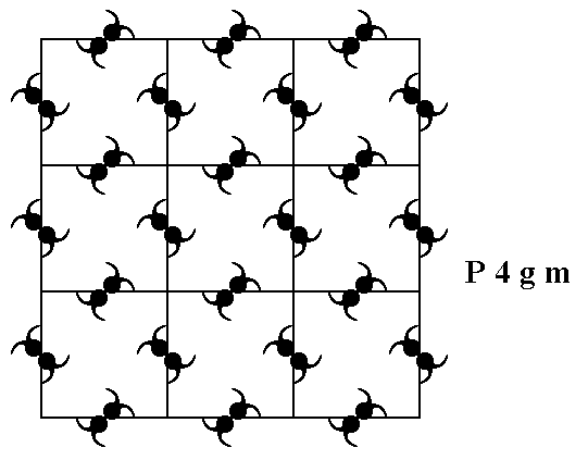
Figure 1. A periodic pattern of motifs based on a 2-D square lattice (net). This particular pattern represents the Plane Group P4gm . It must be imagined to extend indefinitely over the 2-D plane.
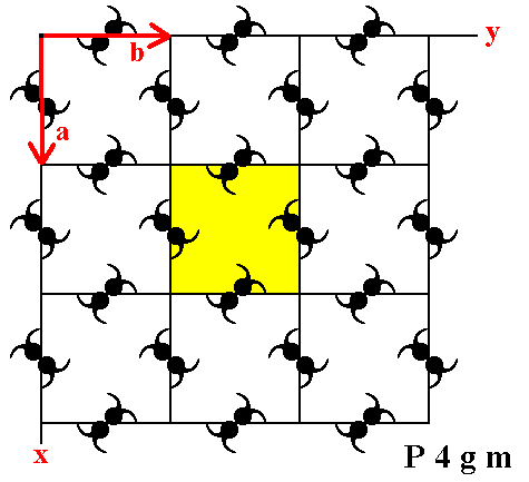
Figure 2. A unit mesh choice for the above pattern is given in yellow.
The pattern consists of some element (i.e. a proper motif, already present in, but yet to be found and indicated) which is repeated by translation vector a in the direction x , and by translation vector b in direction y. In the present case (i.e. in all P4gm patterns) the length of a is equal to that of b.
When we eliminate all translations from the pattern of Figure 1, i.e. when we telescope the structure inward till all translations are zero, the following figure (shape) emerges :
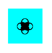
Figure 3. The symmetry of this figure expresses the point symmetry associated with the Plane Group P4gm. It is the translation-free residue of this Plane Group.
The point symmetry of this Figure is 4mm, so the translation-free symmetry of the pattern of Figure 1, i.e. the point symmetry associated with it, is 4mm. This point symmetry is the external symmetry of the structure. It is the macroscopically visible symmetry, because the translations are too small to be detected by the naked eye (We here imagine 2-D crystals to exist in reality and consisting of atoms, ions, or complexes thereof, like 3-D crystals do).
As can be seen in Figure 1 the 'motif '  is not repeated, because its orientation differs from place to place. So we must still find out what in fact is the motif that has been exactly repeated throughout the structure.
In the next Figure the structure is again depicted, but now some areas are highlighted in order to assist our search for the repeated motif, i.e. the genuine motif.
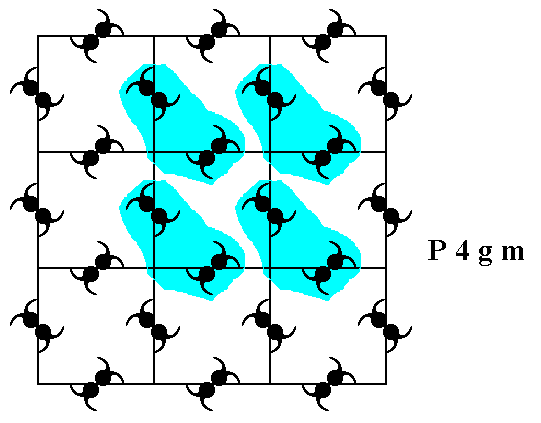
Figure 4. Some areas in the pattern, representing Plane Group P4gm , are highligted in order to determine the actual motif that is being repeated throughout the structure.
Each highlighted area can be thought to be associated with a node of the net. So there should be much more such areas, each one of them associated with a node. In this way the nodes remain equivalent to each other, also when -- as in the present case -- motifs are inserted in the net.
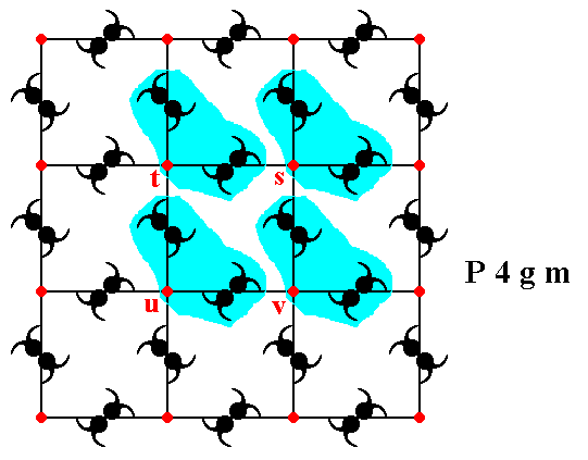
Figure 5. The association of the four highlighted areas with the nodes (red) s, t, u, v of the square net. Each node must have such an associated area, in order to remain equivalent.
Figure 6 determines the actual motifs that are being repeated. These genuine motifs each consist of the motif s.str. (itself consisting of several motif units) and its corresponding surroundings, together making up the motif s.l. . One such motif is depicted.
Figure 6. A motif (blue + content), when repeated along the vectors a and b (See Figure 2), generates the periodic pattern of Figure 1.
The next Figure illustrates four such motifs.
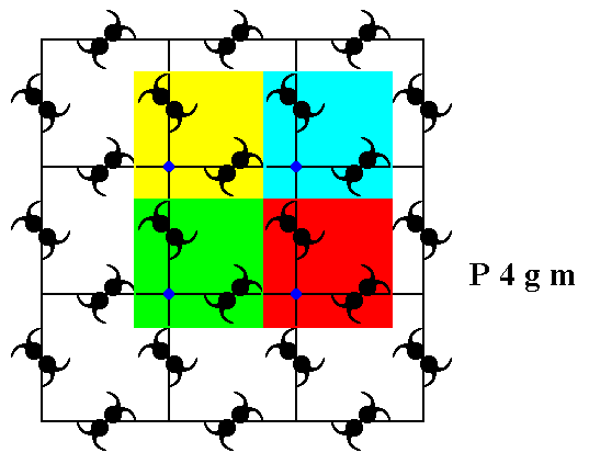
Figure 7. Four genuine equivalent motifs (highlighted by coloration), each associated with a lattice node.
Not only these four lattice nodes, but every node is in fact associated with such a motif. The symmetry of the motif is m , i.e. it possesses one mirror line as its only symmetry element.
Let's consider the equivalence and non-equivalence of points (lattice nodes and other points) in the pattern representing the Plane Group P4gm. See Figure 8.
Figure 8. The pattern representing the Plane Group P4gm . Some points (lattice nodes and other points) are indicated by letters.
If we interpret point s as a lattice point, then point t is equivalent to point s, and they are also equivalent to the points u and v. So s t u v can be chosen as the outline of the unit mesh.
 at its left and right are oriented North-West---South-East, while they are oriented North-East---South-West left and right from point s, and the same goes for the points t, u and v. Consequently the unit mesh is not centered, the mesh is primitive (P).
We're now going to determine the total symmetry content of the pattern -- as depicted in Figure 1 -- representing the Plane Group P4gm.
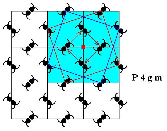
Figure 9. There is a 4-fold rotation axis at every lattice node. One of them is shown.
The next Figure shows that there is also a 4-fold rotation axis at the center of each square defined by the lattice nodes. Also these axes are perpendicular to the plane of the drawing.
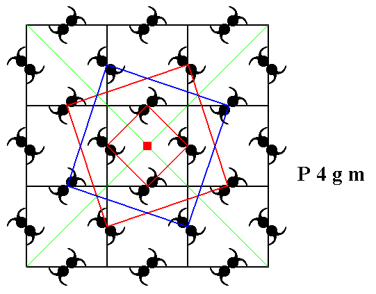
Figure 10. The center of each square defined by the lattice nodes contains a 4-fold rotation axis. One is shown.
From Figures 8 and 11 it is clear that point n (lying exactly between points s and t) contains a 2-fold rotation axis, as well as any other point equivalent to n.
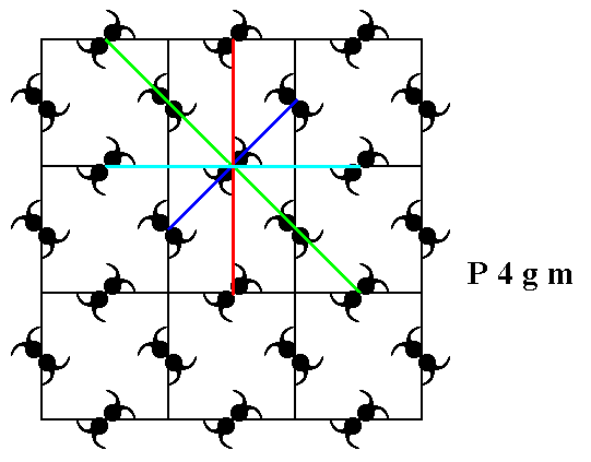
Figure 11. A 2-fold rotation axis goes through point n (Figure 8), as well as through any other point that is equivalent to n .
As further symmetry elements we can detect mirror lines. In the pattern representing Plane Group P4gm we can see one type of mirror line, namely diagonal mirror lines. Non-diagonal mirror lines are not supported by the pattern. See Figure 12.
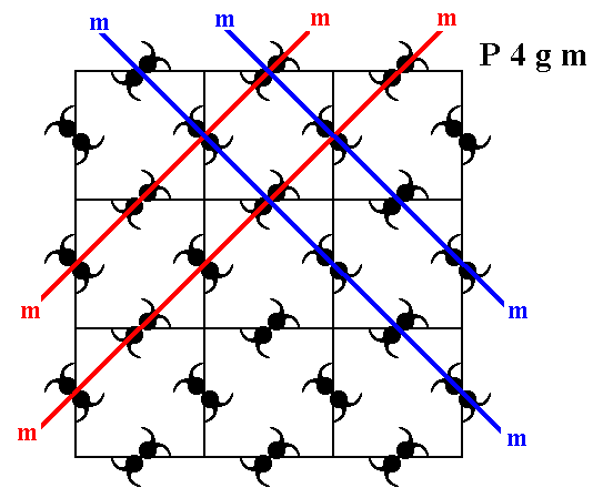
Figure 12. The pattern representing Plane Group P4gm has diagonal mirror lines (m).
Four of them are depicted.
The pattern representing the Plane Group P4gm also has glide lines (glide reflections), diagonal and non-diagonal glide lines. See Figures 13, 14, 15 and 16.
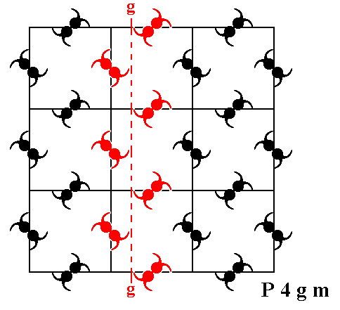
Figure 13. The pattern representing Plane Group P4gm has non-diagonal glide lines (g). One of them is depicted (dashed line).
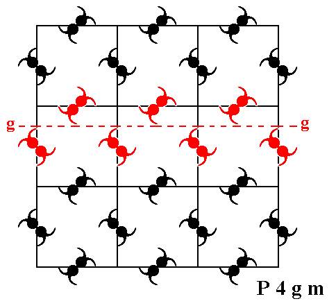
Figure 14. The pattern representing Plane Group P4gm has further non-diagonal glide lines (g). One of them (perpendicular to the one depicted just above) is shown (dashed line).
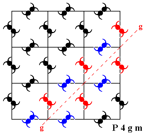
Figure 15. The pattern representing Plane Group P4gm has also diagonal glide lines (g). One of them (at 450 to the one depicted just above) is shown (dashed line).
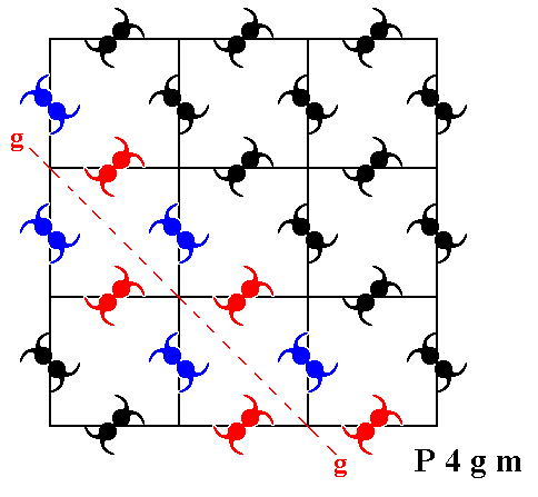
Figure 16. The pattern representing Plane Group P4gm has further diagonal glide lines (g). One of them (perpendicular to the one depicted just above) is shown (dashed line).
In the next Figure we depict the total symmetry content of patterns representing the
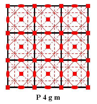
Figure 17. Total symmetry content of the Plane Group P4gm.
Glide lines are indicated by red dashed lines.
Mirror lines are indicated by red solid lines.
4-fold rotation axes are indicated by small red solid squares.
2-fold rotation axes are indicated by small red solid ellipses.
The generation of the group elements of the Plane Group P4gm
We're now going to discuss the generation of the Group from some initial group element, by (repeatedly) applying some generator elements to it and to the results.
In the P4gm pattern as depicted in Figure 1 we see motifs (or motif units for that matter) like  .
.
Such a motif can be considered to consist of four ultimate motif units (partly overlapping commas). Each such comma (ultimate motif unit), which has itself no symmetry, must be considered to represent a group element (When we want to express the Group's total symmetry in its generation, we must generate it from scratch, i.e. generate it from an asymmetric initial motif unit. This motif unit is our comma. Its location and orientation expresses the particular group element as being a particular (rigid) transformation of an initial (ultimate) motif unit). Later we will, as we did in the foregoing documents, determine the maximum area associated with each comma, an area that tiles the plane, and let such an area (containing a comma and its corresponding background) represent a group element.
But first we consider commas only. They represent group elements, among which we choose an initial element (identity element) and a set of generator elements.
The next Figure depicts two chosen generators :
The element (motif unit) m resulting from the element 1 (chosen to represent the identity element), by reflecting it in the mirror line m .
The element (motif unit) p resulting from the element 1 , by rotating it 900 anticlockwise about the point R .
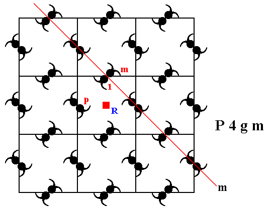
Figure 18. The two chosen generators of the group P4gm (and with it of the corresponding pattern, where the generated group elements are represented by motif units).
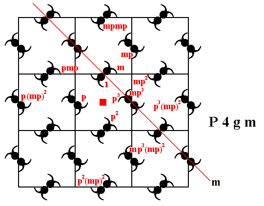
Figure 19. The P4gm pattern can be generated by the two elements m and p.
We will now determine the corresponding background of each (ultimate) motif unit, in order to arrive at an area, containing one motif unit, an area that tiles (not necessarily periodically) the plane without any gaps, and thus an area that can (like its comma) represent a group element.
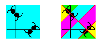
Figure 20. The motif s.l. as chosen in Figure 6 (left image of present Figure) cannot be partitioned into equally sized and equally shaped areas, each containing an ultimate motif unit of the motif s.str., as the right image shows. So this particular choice of motif s.l. is not suited to obtain the maximum ultimate motif units as (maximum) areas representing group elements.
The equally sized and equally shaped areas, each legitimately representing a group element, can be obtained (by division) from a unit mesh considered as motif s.l. (See Figure 2).
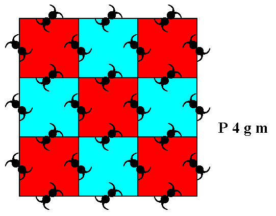
Figure 21. A choice of motifs s.l. (blue and red squares) of the P4gm pattern of Figure 1. Such a motif s.l. consists of eight motif units (represented by commas) PLUS corresponding background. See also next Figure.
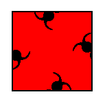
Figure 22. An isolated motif s.l. of the P4gm pattern of Figure 1.
The motif s.l. as chosen in Figure 21 and 22 can be partitioned in equally sized and shaped areas containing one ultimate motif unit s.str. (or one that can represent it). And such an area can legitimately represent a group element.
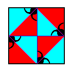
Figure 23. Partition of the newly chosen motif s.l. into areas that can represent group elements.
The next Figure shows this partition for a (larger) part of our P4gm pattern.
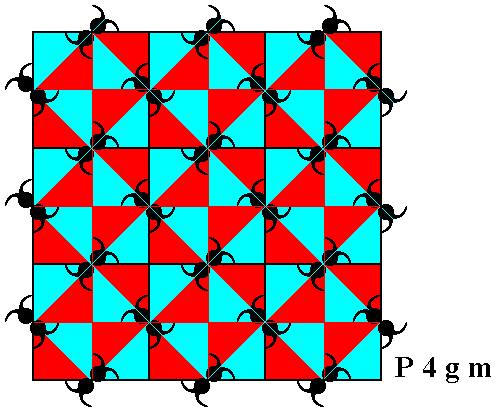
Figure 24. Partition of the P4gm pattern of Figure 1. Each motif s.l. , as established in Figure 21, is divided into eight triangular areas (blue and red) that represent group elements. Each such area contains one (ultimate) unit of the motif s.str. The different colors do not signify qualitative differences.
In the next document we will continue our investigation concerning the generation of this same Plane Group P4gm .
e-mail : 
To continue click HERE for further study of the totally dynamic and holistic nature of Reality.
back to homepage
back to the Ink-in-Glycerine Model
back to Part I of The Crystallization process and the Implicate Order
back to Part II of The Crystallization process and the Implicate Order
back to Part III of The Crystallization process and the Implicate Order
back to Part IV of The Crystallization process and the Implicate Order
back to Part V of The Crystallization process and the Implicate Order
back to Part VI of The Crystallization process and the Implicate Order
back to Part VII of The Crystallization process and the Implicate Order