
e-mail :

Sequel to Group Theory
We'll start with reminding the reader about the "Important Remark" near the end of Part III of Group Theory (To see it, click HERE and then go to (end of) Part III ), a Remark concerning the direction of reading products of group elements, like, say, apq. We read such products (from that Remark onwards) from back to front. Thus (with respect to apq) first q, then p, and then a.
Infinite two-dimensional periodic patterns, or Ornaments (sequel)
In the previous documents we discussed the antisymmetry and subgroups of the symmetry group Pm . As a result of some findings with respect to the possible antisymmetry groups that can be derived from it, we discussed the issue of the ontological status of abstract groups and symmetry groups and of mathematical structures in general.
The plane group Pg .
Now we're going to discuss the plane group Pg with respect to antisymmetry and subgroups.
The next Figure gives this pattern, with the (areas representing) group elements and the unit mesh indicated.
Figure 1. Pattern representing the plane group Pg .
The areas representing group elements (i.e. a choice of a fundamental region) are indicated (green, yellow). Two possible equivalent choices of a unit mesh (unit cell) of the primitive rectangular point lattice are highlighted (blue). Here the colors (green, yellow) do not (yet) signify symmetry features, but only serve to let the group elements clearly stand out.
We will now derive from the above Pg pattern an antisymmetry pattern by replacing the two generating translations by the corresponding antisymmetry transformations, where we let the antiidentity transformation to be the color permutation e1 = (Red Blue) (cycle notation) with respect to the background color only, i.e. we (for reasons of convenience) restrict the color swap to the color of the background of the (black) motifs s.str. (commas). We set the initial color of this background to the color blue. See next Figure.
Figure 2. The Pg pattern of the previous Figure. The initial color of the background is set to be blue. The identity element is indicated (1) . From this pattern the antisymmetry group -- as defined above -- will be derived. See next Figure.
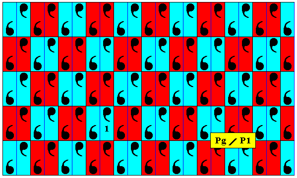
Figure 3. Antisymmetry pattern Pg / P1 derived from the Pg pattern of the previous Figure, by replacing the two generating translations by the corresponding antisymmetry transformations, while not replacing the glide reflection. The antiidentity transformation is defined as the color permutation (Red Blue) with respect to the background color. The result is a checkerboard-like pattern.
As in all similar cases of antisymmetry, the antisymmetry group Pg / P1 is, if not interpreted as an antisymmetry group, just a P1 group, as the next Figure shows.
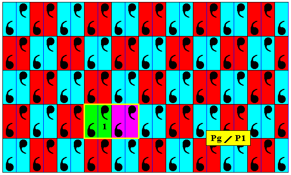
Figure 4. The full group, as presented in this Figure, is, when not interpreted as an antisymmetry group, just a group isomorphic to the plane group P1 . A unit cell for this group is outlined by a yellow rectangle, containing four motifs s.str. The two halfs of this unit cell are not related to each other by a translation. The whole pattern is generated when this unit cell is translated (1) parallel to and equal to the horizontal side of this unit cell, and (2) translated along an oblique direction. And because the different colors signify symmetry features, the glide reflection relating two motif units, is not a transformation of the whole pattern. So the content of the unit cell is -- with respect to the whole pattern -- asymmetric, and generates the whole pattern by it being translated along the two mentioned independent directions, which proves the whole group to be a P1 group. For its lattice, see below (Figure 8b).
We will now investigate what the symmetry is of the subgroup associated with the antisymmetry group just derived, in order to determine the identity of that antisymmetry group, i.e. to determine its symbol.
Figure 5. In the Pg pattern of Figure 2 we here show that pattern to have a symmetry according to the glide line indicated by a dashed line. There are many such glide lines parallel to the latter.
In the next Figure we isolate the subgroup which is associated with the above derived antisymmetry group.
Figure 6. Subgroup associated with the antisymmetry group of Figure 3.
In the next Figure we indicate equivalent points in the pattern of the subgroup depicted in the previous Figure.
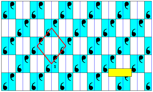
Figure 7. The pattern of the subgroup associated with the above antisymmetry group has equivalent points. Four of them are indicated at the corners of a rhombus.
From the above Figure one could think that we have to do with a pattern based on a rhombic lattice. But, as we will show, the motifs in this pattern are not compatible with a rhombic lattice (or, equivalently, with a centered rectangular lattice).
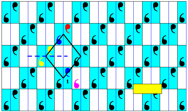
Figure 8. Pattern of previous Figure. The yellow commas are related to each other by a glide reflection according to the glide line indicated (dashed line), so also the dark blue commas (See Figure 5 for the meaning of a glide reflection for a whole pattern). But the red comma (colors do not signify symmetry features) of the same pattern does not have a counterpart related to it by the same glide line (that counterpart is indicated by a purple comma which, however, does not belong to the pattern). So the glide reflection transformation of the yellow commas (the colors do not signify symmetry features) is not a transformation of the whole pattern. Consequently the two yellow commas -- and all other such pairs -- form an asymmetric motif. And this asymmetric motif is repeated along two independent translations (along the sides of the rhombus), which means that the pattern is isomorphic to the plane group P1 .
So the subgroup is represented by a P1 pattern, implying that the symbol for the antisymmetry group (Figure 3) -- with which this subgroup is associated -- must be Pg / P1 .
The next Figures indicate the respective point lattices of the generating Pg pattern of Figure 2 and of the above derived antisymmetry pattern Pg / P1 ( Figure 3 ).
Figure 8a. Point lattice (indicated by connection lines) of the generating Pg pattern of Figure 2. It is a primitive rectangular lattice (net).
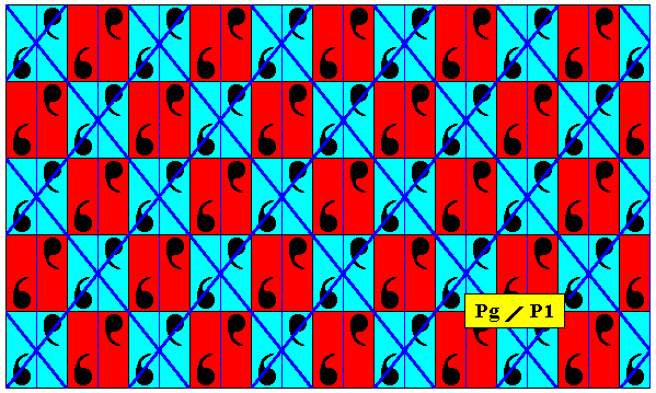
Figure 8b. Point lattice (indicated by strong blue connection lines) of the antisymmetry pattern Pg / P1 , derived above ( Figure 3 ) by replacing both generating translations by their corresponding antisymmetry transformations.
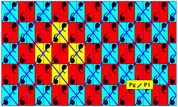
Figure 8c. Four equivalent points (plus surroundings to show this equivalence) highlighted in the point lattice depicted in the previous Figure. We see that the lattice points are associated with an asymmetric motif, indicating that we here have not to do with a rhombic lattice, but with an oblique lattice ( The latter is a generalization of the rhombic lattice). It is an oblique lattice that happens to have rhombic meshes. The asymmetric motifs, however, are not compatible with a genuine rhombic lattice, but with an oblique lattice.
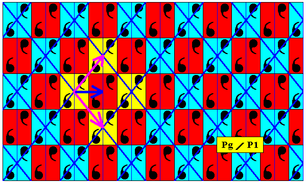
Figure 8d. Pattern of previous Figure.
The two translation vectors are indicated by purple arrows.
The dark blue arrow is not a translation.
The yellow areas indicate four equivalent points. In the same way also the red areas represent equivalent points. Differently colored areas are, however, not equivalent.
In spite of the fact that the above pattern (Figure 8d) is just an asymmetric motif that is translated along two independent directions (explicitly indicated in Figure 8g below, where we see that in total a red as well as a blue area is being translated), and thus being a P1 pattern, the lattice is regular, i.e. the lattice in itself implies rhombic meshes. Ands this regularity results from the fact that our pattern is an a n t i s y m m e t r y p a t t e r n derived from a pattern having a higher symmetry than just a P1 pattern. So by means of the concept of antisymmetry we can express the vestige of symmetry in a particular P1 pattern, that happens to have that vestige, while many other P1 patterns do not have this vestige. The latter are just asymmetric motifs translated along two different oblique directions and along different distances (i.e. with different lengths of the translation vectors).
It is instructive to compare the translations of the antisymmetry pattern of the previous Figure with those of the generating Pg pattern of Figure 8a.
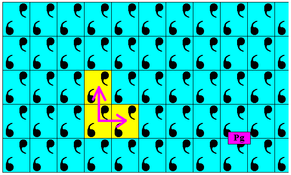
Figure 8e. Translations (indicated by purple arrows) of the generating Pg pattern of Figure 8a. They are perpendicular to each other.
The next Figure shows a unit mesh of the antisymmetry pattern of Figure Figure 8b.
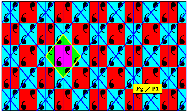
Figure 8f. Unit mesh (indicated by yellow outline and alternative colors) of the antisymmetry pattern under discussion (Figure 8b).
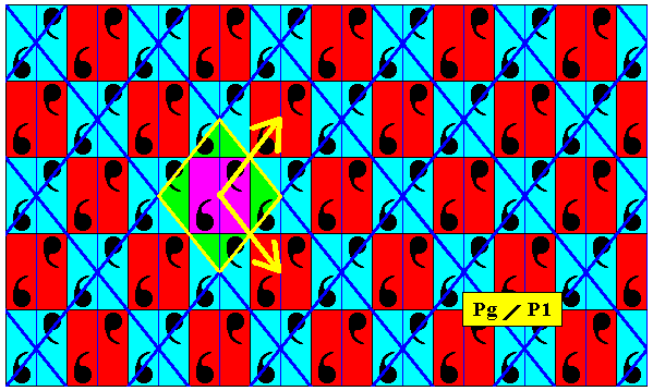
Figure 8g. In this Figure we can clearly see that the pattern under discussion (Figure 8b) consists just of a translational repetition of an asymmetric motif : The asymmetric content of a rhombus is translated in two independent directions according to the two translation vectors indicated by yellow arrows. It is therefore a P1 pattern. But because this pattern allows an interpretation in terms of antisymmetry, namely it being an antisymmetry pattern derived from a Pg pattern, it is isomorphic to the latter. So if we have a particular P1 pattern, i.e. a pattern determined as a P1 pattern according to classical symmetry theory, it sometimes allows to be described by the a n t i s y m m e t r y t h e o r y as a pattern with a symmetry isomorphic to Pg symmetry (instead of P1 ) , which fact is expressed by indicating that pattern by the antisymmetry symbol Pg / P1 . So in many cases antisymmetry allows us to dig a little deeper into the symmetry of a given pattern.
Another antisymmetry pattern (but representing the same antisymmetry group) can be obtained from a Pg pattern by replacing the generating glide reflection by the corresponding antisymmetry transformation. In this we let the antiidentity transformation e1 again be the color permutation (Red Blue) (cycle notation) with respect to the background color (i.e. the color of the space in which the motifs s.str. are embedded). The other generators are not replaced. The result is depicted in the next Figure.
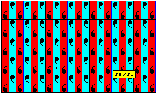
Figure 9. Antisymmetry pattern Pg / P1 derived from the Pg pattern of Figure 2 by replacing the generating glide reflection by the corresponding antisymmetry transformation, while letting the other generators unreplaced.
As can be seen from the above Figure, the set of 'blue' elements (containing the identity element) forms a subgroup that is isomorphic to P1, because we have here an asymmetric motif that is translated along two independent directions, while moreover these translations are also elements of the full group. Therefore the symbol of the present antisymmetry group must be Pg / P1 .
The next Figure gives the point lattice underlying the above derived antisymmetry pattern.
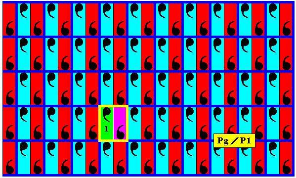
Figure 9a. Point lattice (indicated by strong dark blue connection lines) of the above derived (Figure 9) antisymmetry pattern. A unit mesh is indicated by yellow outline and alternative colors. Compare with the point lattice of the generating Pg pattern of Figure 8a. Compare also with the antisymmetry pattern of Figure 8b to which the present antisymmetry pattern is group theoretically isomorph.
Another antisymmetry pattern, now with the antisymmetry group Pg / Pg , can be obtained from the Pg pattern, by replacing the vertical generating translation by the corresponding antisymmetry transformation, where the antiidentity transformation e1 is again the color permutation (Red Blue) (cycle notation) with respect to the background color. The next Figure gives the result.
Figure 10. Antisymmetry pattern Pg / Pg , derived from the Pg pattern of Figure 2 by replacing the vertical generating translation by the corresponding antisymmetry transformation.
The next three Figures show that the subgroup associated with the present antisymmetry group is isomorphic to Pg , i.e. it is isomorphic to the full group. Therefore the symbol of the corresponding antisymmetry group (Figure 10) must be Pg / Pg .
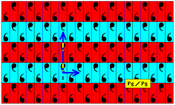
Figure 11. Generating translations of the subgroup (blue elements) of the antisymmetry group Pg / Pg .
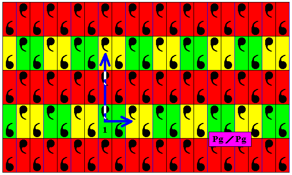
Figure 12. In the s u b g r o u p of the antisymmetry group Pg / Pg the same structural unit as that of the generating group Pg (See Figure1) is repeated by two translations. One of these translations (the horizontal one) is identical to the horizontal generating translation of the generating group (and of the antisymmetry group), while the other translation (the vertical one) is identical to two times the vertical translation of the generating group (implying that the subgroup has Pg symmetry, while the unit mesh of the pattern representing this subgroup is two times higher than the one of the generating pattern, i.e. the full group). So the translations of the subgroup are also elements of the full group (which must be the case, for it to be a subgroup).
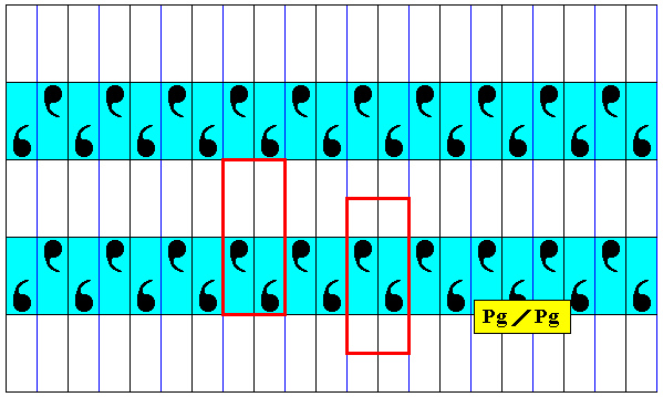
Figure 12a. The above indicated subgroup isolated. Two alternative choices of unit mesh are given. The one to the right clearly shows that the pattern consists of periodic repetitions of a unit pattern that itself consists of two parts related to each other by a single horizontal glide reflection, implying that the whole subgroup pattern has Pg symmetry.
The next Figure gives the point lattice of the above derived antisymmetry pattern.
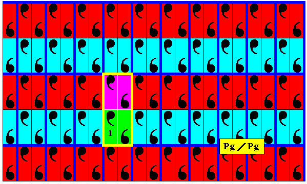
Figure 12b. Point lattice (indicated by strong dark blue connection lines) of the above derived antisymmetry pattern Figure 10. A unit mesh is indicated by yellow outline and alternative colors. Compare with the point lattice of the generating Pg pattern of Figure 8a.
Finally, we can derive an antisymmetry pattern from our Pg pattern by replacing the horizontal generating translation by its corresponding antisymmetry transformation (antisymmetry translation) with the same interpretation of the antiidentity transformation e1 as before. See next Figures.
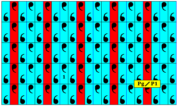
Figure 12c. Antisymmetry pattern derived from the generating Pg pattern of Figure 2 by replacing the generating horizontal translation by its corresponding antisymmetry transformation.
If we look to the blue elements (among which is the identity element) of the just derived antisymmetry pattern, we see that the horizontal glide reflection is destroyed because elements are missing. So the symmetry that is left over is a horizontal translation over two times a distance of the corresponding translation in the generating pattern (Pg) ( This translation is an element of the generating group, the full group), and a vertical translation identical to the original one. This implies that the set of blue elements is a subgroup of the generating pattern and that its symmetry is isomorphic to that of the plane group P1. So the symbol for the corresponding antisymmetry group (Figure 12c) must read Pg / P1 .
The next Figures give the point lattice of the just derived antisymmetry pattern.
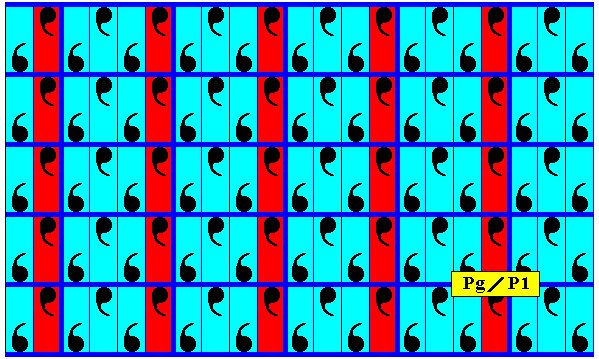
Figure 12d. Point lattice (indicated by strong dark blue connection lines) of the above derived antisymmetry pattern (Figure 12c).
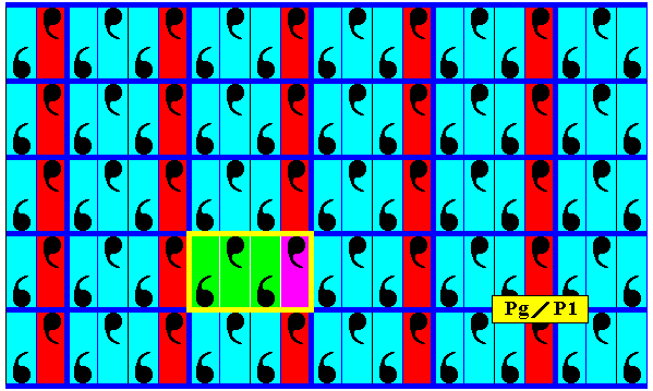
Figure 12e. Point lattice (indicated by strong dark blue connection lines) of the above derived antisymmetry pattern (Figure 12c). A unit mesh is indicated by yellow outline and alternative colors.
Subgroups of the plane group Pg
Here we will show some subgroups of the plane group Pg not necessarily associated with antisymmetry or colored symmetry.
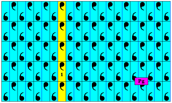
Figure 13. Subgroup (yellow) p11 (which is a line group that can be represented by a frieze pattern) of the plane group Pg .
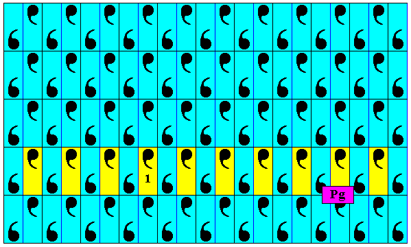
Figure 14. A second p11 subgroup (yellow) of the plane group Pg .
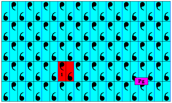
Figure 15. This (red) is not a subgroup of the group Pg , because when the glide reflection is repeated, we end up outside the confines of the two elements (indicated by red), and thus outside the confines of the alleged subgroup. Only when the non-identity element is involute, i.e. when its period is 2, such a two-element set will be a group.
The next plane group we will consider with respect to antisymmetry and subgroups is the group P2mm .
Figure 16. A pattern representing the plane group P2mm . The areas representing group elements are indicated (green, yellow). Here the colors do not signify symmetry features, but only serve to indicate the group elements. A unit mesh (unit cell) is highlighted (blue). It indicates the primitive rectangular lattice underlying the pattern, and contains four units of the motif s.str. This motif s.str. is a rosette with symmetry group D2 .
For the derivation of antisymmetry patterns, we set -- in the next Figure -- the initial color of the background (i.e. of the background of the (black) commas) as being blue, and choose as generators two reflections, one in a horizontal ( mh ), and another in a vertical ( mv ) reflection line, and two translations, one horizontal ( th ) and another vertical ( tv ). See next Figure.
Figure 17. Generators and initial background color of the pattern of the previous Figure.
From the above P2mm pattern the first antisymmetry group will be derived by replacing the generating vertical translation tv by the corresponding antisymmetry transformation e1tv , where e1 will be taken to mean the color permutation (Red Blue) (cycle notation) with respect to the background color. The other generators are not replaced. The next Figure gives the result.
Figure 18. Antisymmetry pattern P2mm / P2mm derived from the (above depicted pattern representing the) generating symmetry group P2mm .
In the above Figure we clearly see that the set of blue elements (containing the identity element) is a D2 rosette that is repeated by two perpendicular translations (both also -- as symmetry transformations -- belonging to the full group). So this subgroup is a P2mm pattern, implying that the symbol for the corresponding antisymmetry group must be P2mm / P2mm .
The next Figures give the respective point lattices of the generating P2mm pattern and of the above derived antisymmetry pattern.
Figure 18a. Point lattice (indicated by connection lines) of the generating P2mm pattern of Figure 16.
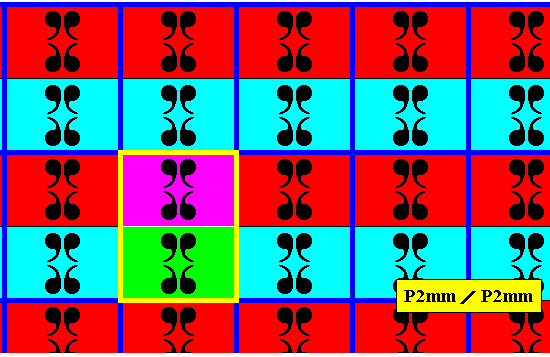
Figure 18b. Point lattice (indicated by strong dark blue connection lines) of the antisymmetry pattern derived above (Figure 18). A unit mesh is indicated by yellow outline and alternative colors.
A second antisymmetry group can be derived from our P2mm pattern by replacing the horizontal generating translation th by its corresponding antisymmetry transformation e1th , where the antiidentity transformation e1 is again taken to be the color permutation (Red Blue) (cycle notation). The next Figure gives the result.
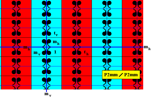
Figure 19. Antisymmetry pattern P2mm / P2mm derived from the generating P2mm pattern of Figure 17.
In the above Figure we clearly see that the set of blue elements (containing the identity element) is a D2 rosette that is repeated by two perpendicular translations (both also -- as symmetry transformations -- belonging to the full group). So this subgroup is a P2mm pattern, implying that the symbol for the corresponding antisymmetry group must be P2mm / P2mm .
The next Figure gives the point lattice of the just derived antisymmetry pattern (Figure 19).
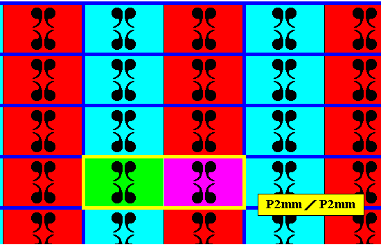
Figure 19a. Point lattice (indicated by strong dark blue connection lines) of the antisymmetry pattern of Figure 19. A unit mesh is indicated by yellow outline and alternative colors. Compare with the point lattice of the generating P2mm pattern of Figure 18a.
A third antisymmetry group can be derived from the P2mm pattern of Figure 17 by replacing the horizontal reflection mh by the corresponding antisymmetry transformation e1mh , where the antiidentity transformation e1 is again taken to be the color permutation (Red Blue) (cycle notation) of the background color. The other generators are not replaced. The next Figure gives the result.
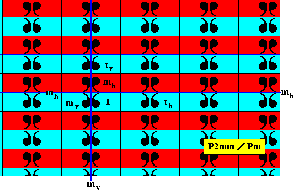
Figure 20. Antisymmetry pattern P2mm / Pm derived from the generating P2mm pattern of Figure 17.
In the above Figure we clearly see that the set of blue elements (containing the identity element) is a D1 rosette that is repeated by two perpendicular translations (both also -- as symmetry transformations -- belonging to the full group). So this subgroup is a Pm pattern, implying that the symbol for the corresponding antisymmetry group must be P2mm / Pm .
The next Figure gives the point lattice of the just derived antisymmetry pattern (Figure 20).
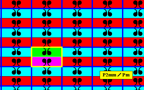
Figure 20a. Point lattice (indicated by strong dark blue connection lines) of the antisymmetry pattern of Figure 20. A unit mesh is indicated by yellow outline and alternative colors. Compare with the point lattice of the generating P2mm pattern of Figure 18a.
A fourth antisymmetry group can be derived from the P2mm pattern of Figure 17 by replacing the vertical reflection mv by the corresponding antisymmetry transformation e1mv , where the antiidentity transformation e1 is again taken to be the color permutation (Red Blue) (cycle notation). The other generators are not replaced. The next Figure gives the result.
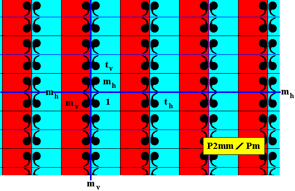
Figure 21. Antisymmetry pattern P2mm / Pm derived from the generating P2mm pattern of Figure 17.
In the above Figure we clearly see that the set of blue elements (containing the identity element) is a D1 rosette that is repeated by two perpendicular translations (both also -- as symmetry transformations -- belonging to the full group). So this subgroup is a Pm pattern, implying that the symbol for the corresponding antisymmetry group must be P2mm / Pm .
The next Figure gives the point lattice of the just derived antisymmetry pattern (Figure 21).
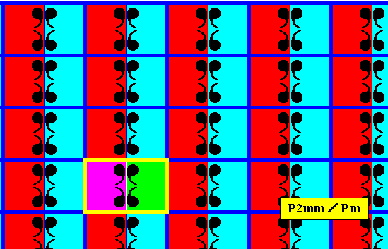
Figure 21a. Point lattice (indicated by strong dark blue connection lines) of the antisymmetry pattern of Figure 21. A unit mesh is indicated by yellow outline and alternative colors. Compare with the point lattice of the generating P2mm pattern of Figure 18a.
A fifth antisymmetry group can be derived from the P2mm pattern of Figure 17 by replacing the vertical reflection mv by the corresponding antisymmetry transformation e1mv , and the vertical translation tv by the corresponding antisymmetry transformation e1tv , where the antiidentity transformation e1 is again taken to be the color permutation (Red Blue) (cycle notation) of the background color. The other generators are not replaced. The next Figure gives the result.
Figure 22. Antisymmetry pattern P2mm / P2mg derived from the generating P2mm pattern of Figure 17. The result is a checkerboard pattern.
The next Figure isolates the subgroup that is involved in the above antisymmetry pattern. It consists of the set of blue elements (containing the identity element).
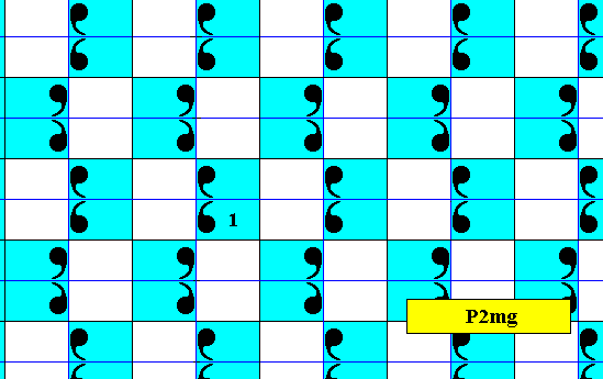
Figure 22a. Isolated subgroup P2mg of the above pattern representing the antisymmetry group P2mm / P2mg (Figure 22).
The next Figures explain the P2mg symmetry of this subgroup.
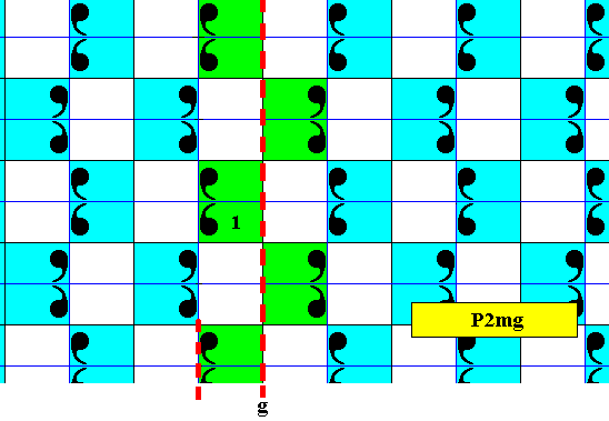
Figure 22b. Illustration of the generating glide reflection of the above derived subgroup, i.e. the subgroup emerging in the antisymmetry pattern of Figure 22. One of the other glide reflection lines is indicated.
The next Figure demonstrates that the pattern representing the subgroup under discussion does not contain horizontal glide reflections, but only vertical glide reflections.
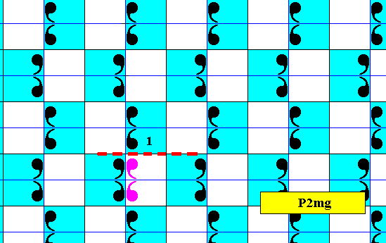
Figure 22c. No horizontal glide reflections are present in the subgroup under discussion.
The next figure shows that there are horizontal mirror lines in the pattern representing the subgroup under discussion. Two such mirror lines are highlighted.
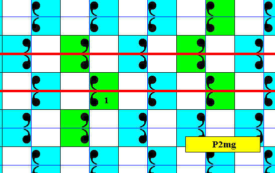
Figure 22d. The subgroup under discussion contains horizontal reflections (Like always, the pattern must be imagined to be extended indefinitely over the plane).
The next Figure gives a unit mesh of the above pattern representing the subgroup under discussion. It contains three vertical glide lines (g), two horizontal mirror lines (m) and nine half-turns (i.e. rotations of 1800). And this is indeed the fingerprint of the plane group P2mg.
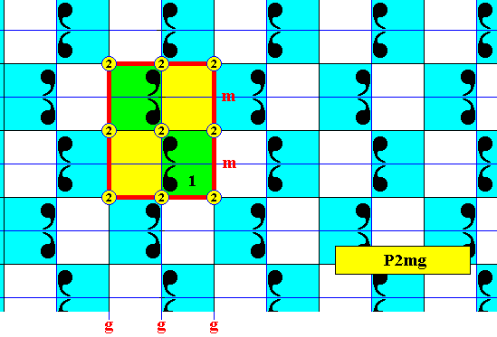
Figure 22e. A unit mesh of the pattern representing the subgroup under discussion (i.e. the subgroup consisting of the set of blue elements as it is present in the antisymmetry pattern of Figure 22 ). The symmetry elements and their configuration, as present in the unit mesh, represent the fingerprint of the plane group P2mg .
Now having determined the symmetry of the subgroup to be that of P2mg , we can determine that the symbol for the antisymmetry group of Figure 22 must be P2mm / P2mg .
The next Figure gives the point lattice of the antisymmetry pattern derived above (Figure 22).
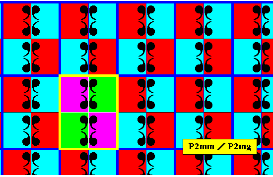
Figure 22f. Point lattice (indicated by strong dark blue connection lines) of the antisymmetry pattern of Figure 22. A unit mesh is indicated by yellow outline and alternative colors. Compare with the point lattice of the generating P2mm pattern of Figure 18a.
We will now show some (more) antisymmetry patterns mathematically derivable from our present symmetry group P2mm , and present in Neolithic ornamental art.
Figure 23. Generating P2mm pattern, from which an antisymmetry pattern, found in ornamental art of the Neolithic, can be derived.
The next Figure shows a unit mesh (by showing in fact two times 25 of them) of the pattern of the previous Figure. We can clearly see that the pattern has P2mm structure.
Figure 24. Two times 25 unit meshes are outlined with respect to the pattern of the previous Figure. The red color serves to extra highlight the unit meshes. One can see that in this pattern a D2 (augmented) motif is repeated along two translations perpendicular to each other, which indicates that the pattern's symmetry is according to the planegroup P2mm .
The next Figure shows a possible antisymmetry pattern, derived from the above (Figures 23 and 24) pattern.
Figure 25. Antisymmetry pattern, derived from the P2mm pattern of Figure 23, and present in ornamental art of the Neolithic. (Adapted from JABLAN, 2002)
In order to analyze the above antisymmetry pattern, we insert in it a part of the lattice as given in Figure 24.
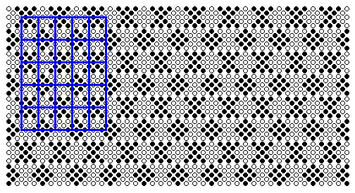
Figure 26. Antisymmetry pattern of Figure 25.
A part of the lattice (25 unit meshes) as determined in Figure 24 is inserted. One can see that it is not an appropriate lattice of the antisymmetry pattern, because the meshes and their content are not repeated periodically.
The next Figure shows that four former unit meshes (i.e. the unit meshes of the generating pattern [Figure 24]) taken together, are needed to form a unit mesh of the antisymmetry pattern.
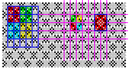
Figure 27. The above antisymmetry pattern still has vertical and horizontal reflection lines. At the left side in the image it is shown that four former lattice meshes are needed to obtain one lattice mesh (unit mesh) of the antisymmetry pattern. The vertical mirror symmetry of the antisymmetry pattern is not expressed by this unit mesh, so it is more convenient to choose a unit mesh (of the same size) as indicated at the right side in the image. This latter unit mesh is bounded by mirror lines of the pattern. In about the middle of the image four areas representing group elements, based on the lastly chosen unit mesh are indicated.
The next Figure shows the lattice based on the unit mesh as indicated in the right-hand part of the previous Figure.
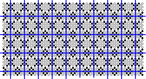
Figure 28. Rectangular point lattice (indicated by connection lines) for the antisymmetry pattern of Figure 25, based on the unit mesh indicated at the right side of the image of the previous Figure.
The next Figure brings it out more clearly.
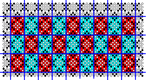
Figure 29. Lattice meshes (red, blue) for the antisymmetry pattern of Figure 25.
( The red and blue colors do not signify symmetry features).
The next Figure indicates the areas representing group elements obtained by dividing each unit mesh by four, along the mirror lines.
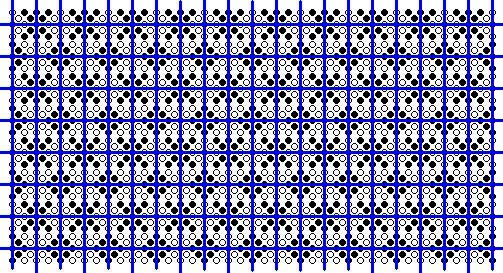
Figure 30. Areas representing group elements of the antisymmetry pattern of Figure 25.
The following Figure highlights these group elements by colors.
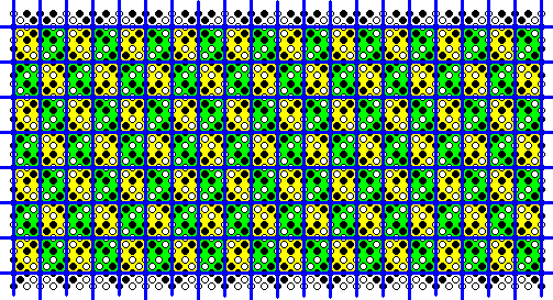
Figure 31. The group elements highlighted by the colors green and yellow, which do not signify symmetry features.
The next Figure shows a blow-up of a part of the image in Figure 30.
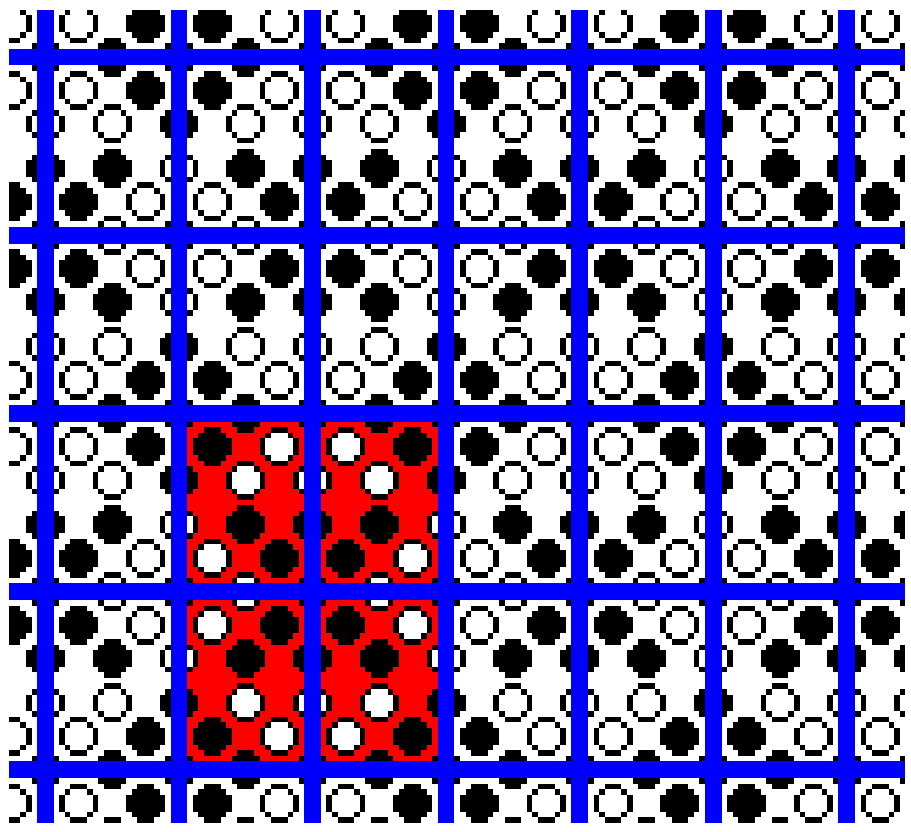
Figure 32. Magnification of a part of the image of Figure 30.
A unit mesh (red) is indicated. It consists of four (areas that represent) group elements.
As can be seen in the above Figures, a fundamental region, and thus an area that represents a group element must be rectangular in virtue of the two generating reflections. So we cannot change its shape, which implies that such an area always contains white as well as black circles (belonging to the motif s.str.). And this means that we cannot identify an area representing a group element without white-circles-having-been-changed-to-black-circles, i.e. a group element representing area with white circles only (which was the initial color state [See Figure 23] ), which in turn means that we cannot find the identity element for the antisymmetry group. So the conclusion must be that our 'antisymmetry pattern' is not an antisymmetry pattern at all, despite the fact that it is given as such in JABLAN, S., 2002, Symmetry, Ornament and Modularity, p.144, Fig. 2.107 ( l ). The alleged antisymmetry pattern is just (another) P2mm pattern.
In the next document we will continue with the present group (P2mm), before considering the remaining plane groups.
e-mail : 
To continue click HERE for further group theoretic preparation to the study of the structure of three-dimensional crystals (crystallography) and the basic symmetry of organisms (promorphology).
Back to 3-dimensional crystals (conclusion), Organic Tectology and Promorphology
Back to subpatterns and subgroups (introduction)
Back to subpatterns and subgroups Part II
Back to subpatterns and subgroups Part III
Back to subpatterns and subgroups Part IV
Back to subpatterns and subgroups Part V
Back to subpatterns and subgroups Part VI
Back to subpatterns and subgroups Part VII
Back to subpatterns and subgroups Part VIII
Back to subpatterns and subgroups Part IX
Back to subpatterns and subgroups Part X
Back to subpatterns and subgroups Part XI
Back to subpatterns and subgroups Part XII
Back to subpatterns and subgroups Part XIII