
e-mail :

Sequel to Group Theory
As always, we start with reminding the reader about the "Important Remark" near the end of Part III of Group Theory (To see it, click HERE and then go to (end of) Part III ), a Remark concerning the direction of reading products of group elements, like, say, apq. We read such products (from that Remark onwards) from back to front. Thus (with respect to apq) first q, then p, and then a.
Infinite two-dimensional periodic patterns, or Ornaments (sequel)
The Plane Group P4mm
In the present document we will study antisymmetry, subpatterns and subgroups in patterns that represent the plane group P4mm.
Figure 1. Pattern representing plane group P4mm . The motifs s.str. are (chosen to be) a set of eight units, and as such placed inside the (square) lattice meshes. The units in a mesh are related to each other by a 4-fold rotation axis and two pairs of mirror lines. One eighth of a square lattice mesh can represent a fundamental region (yellow or green), containing an asymmetric unit of the motif s.str. . As such these regions can represent group elements. A lattice mesh is indicated (blue). The pattern must be imagined to extend indefinitely over the plane. It will represent the g e n e r a t i n g P4mm s y m m e t r y p a t t e r n from which we will derive a n t i s y m m e t r y patterns.
Before we're going to derive antisymmetry patterns, we will -- in the following -- first determine the point lattice and generators of our generating P4mm pattern (Figure 1), and also the distribution of its symmetry elements (rotation axes, glide lines and mirror lines).
Figure 2. Same as previous Figure : The generating P4mm symmetry pattern. Background color set to blue.

Figure 2. The generating P4mm symmetry pattern.
The two meshes indicated (yellow) cannot represent a lattice of this pattern, because they do not repeat in the direction of the translation implied by these meshes.
The next Figure gives the point lattice of the generating P4mm symmetry pattern.
Figure 3. Point lattice (indicated by strong dark blue connection lines) of the generating P4mm symmetry pattern. A unit mesh is indicated (blue). The lattice is a square point net. Background color changed to yellow, in order to let the lattice connection lines stand out clearly.
The next two Figures show the distribution of the symmetry elements (rotation axes, mirror lines, glide lines) of the generating P4mm symmetry pattern.
Figure 4. Symmetry elements of the generating P4mm pattern.
Shown are :
The pattern's glide lines are indicated in the next Figure.

Figure 5. Symmetry elements of the generating P4mm pattern.
Glide lines (indicated by thick purple lines).

Figure 6. Illustration of a glide line ( g ) in the generating P4mm symmetry pattern.
The distribution of the symmetry elements in the generating symmetry pattern is indeed the fingerprint of the plane group P4mm.
We will now determine a set of possible generators of the generating P4mm symmetry pattern.
The next Figure proposes a set of possible generators that can generate the whole P4mm pattern.
Figure 7. A set of generators for the P4mm pattern is proposed :
p ( 900 anticlockwise rotation) about the point indicated by a small solid red square.
The next Figures show how the P4mm pattern can be generated by applying the above given generators.
Figure 8. First stage of the generation of the P4mm pattern.
The identity element is reflected in the line mse .
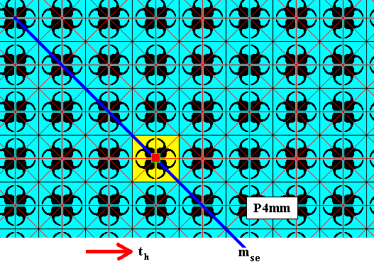
Figure 9. Second stage of the generation of the P4mm pattern.
The two elements obtained above (1, mse) are subjected to the rotations p, p2 and p3 , resulting in a D4 rosette (yellow), consisting of eight group elements.

Figure 10. Third stage of the generation of the P4mm pattern.
The elements already obtained above are subjected to the horizontal translation th , resulting in an infinite horizontal band of group elements.

Figure 11. Fourth stage of the generation of the P4mm pattern.
Elements already obtained above are reflected in the line mse , resulting in still more elements.

Figure 12. Fifth and final stage of the generation of the P4mm pattern.
The elements already obtained above are subjected repeatedly to the horizontal translation th , resulting in the whole pattern.
So indeed {p, mse , th } is a valid set of generators for the P4mm pattern.
We are now ready to derive antisymmetry patterns from our P4mm pattern.
The first antisymmetry pattern to be derived from the generating P4mm symmetry pattern as it is depicted in Figure 2 and Figure 7 can be obtained by replacing the generating rotation p (900 anticlockwise rotation about the axis indicated in the above Figures) by its corresponding antisymmetry rotation e1p , where the antiidentity transformation e1 is interpreted as the color permutation (Blue Red) (cycle notation) with respect to the background color, which is set initially as being blue. The other generators are not replaced.
We will derive the antisymmetry pattern in several steps. Newly generated blue elements will initially be colored yellow, and later be restored to blue. Newly generated red elements will initially be colored purple and later be restored to red.

Figure 13. First stage of the derivation of the antisymmetry pattern as defined above.
The identity element is subjected to e1p (= pe1), which means a 900 anticlockwise rotation about the axis indicated by a small solid red square, and implying a color change. If we subject the result again to the transformation e1p , the element e1pe1p (= p2) is generated, which has its color changed back again. If, finally, we subject this result again to e1p , the element e1pe1pe1p (= e1p3) is generated, which has its color again changed.

Figure 14. Second stage of the derivation of the antisymmetry pattern as defined above.
The identity element is subjected to the generating reflection mse not effecting a color change, because this reflection is not an antisymmetry transformation. Repeated application of the antisymmetry rotation e1p to the newly generated element (mse) results in three more elements where color change is involved, as indicated.
In the next Figure we depict this stage again, but now with purple restored to red, and the red lines, representing the boundaries of the areas representing group elements, turned blue (in order for these lines to remain visible when more red elements enter the scene).

Figure 15. Second stage (as in previous Figure) of the derivation of the antisymmetry pattern as defined above.
Purple restored to red. Red lines indicating group element boundaries turned blue for convenience.

Figure 16. Third stage of the derivation of the antisymmetry pattern as defined above.
The generating translation th is applied to the elements obtained earlier.

Figure 17. Fourth stage of the derivation of the antisymmetry pattern as defined above.
The generating reflection mse is applied to the elements obtained earlier. It has the same effect as applying the antisymmetry rotation to these elements ( 900 anticlockwise rotation and color change).

Figure 18. Beginning of fifth stage of the derivation of the antisymmetry pattern as defined above.
The generating horizontal translation th is applied to some elements obtained earlier.

Figure 19. Completion of fifth stage of the derivation of the antisymmetry pattern as defined above.
The generating horizontal translation th is applied to the rest of the elements obtained earlier in Figure 17 .
If we now restore yellow to blue and purple to red we get our antisymmetry pattern.

Figure 20. Antisymmetry pattern derived from the generating P4mm pattern (Figure 7 ) by replacing the generating rotation by its corresponding antisymmetry rotation. The result is a checkerboard-like pattern.
In the next document we will determine the identity of the just derived antisymmetry pattern by looking to its lattice, symmetry elements and subpattern of blue elements.
e-mail :
To continue click HERE for further group theoretic preparation to the study of the structure of three-dimensional crystals (crystallography) and the basic symmetry of organisms (promorphology).
Back to 3-dimensional crystals (conclusion), Organic Tectology and Promorphology
Back to the Beginning of the present Series on Subpatterns and Subgroups. There : LINK to Part XXVII
Back to Part XXVIII of the present Series
Back to Part XXIX of the present Series
Back to Part XXX of the present Series


