The Monoclinic Crystal System (Part One)
(Alternative name : Monosymmetric System)
back to homepage
Introduction
For a general introduction to Crystal Systems and Crystal Classes, see the Essay on The Morphology of Crystals, which the reader should first consult, if he or she is not familiar with Crystal Symmetry and its description.
The reader should also consult the previous Essays on The Tetragonal Crystal System, on The Hexagonal Crystal System and on The Orthorhombic Crystal System in order to fully understand the issues in the present Essay and the next Essays on the Monoclinic System.
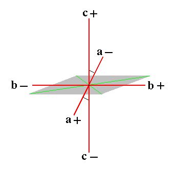
The crystalloghraphic axial system to which the Forms of this Crystal System let themselves refer, consists of two non-equivalent axes (a and c) intersecting each other at an oblique angle (i.e. the angle obtaining between them is not 900), and a third non-equivalent axis (b) which is perpendicular to them and is called the ortho axis (or orthodiagonal). By convention the axial system is oriented such that the ortho axis is horizontal and going from left to right. Of the two other axes one is placed vertically and is called the vertical axis (c), while the other, which is called the clino axis or clinodiagonal (a), is oriented such that its near end (near with respect to the beholder) points obliquely downward (while its far end points obliquely upward). The angle between the clino axis and the vertical axis is indicated by the Greek letter beta and must -- along with the axial ratio -- be indicated in any description because it is different in different substances.
Because the Holohedric Division of this Crystal System has only one mirror plane, the System is also called the Monosymmetric Crystal System. Having such a holohedric crystal, the symmetry axis perpendicular to this mirror plane is (by convention) indicated as ortho axis (b) and the crystal is oriented accordingly (ortho axis horizontal from left to right). For the two oblique axes a and c one takes the directions of two appropriate crystal edges lying in the mirror plane.
The just expounded axial system compatible with crystals of the Monoclinic System is depicted in Figure 1.
 |
|
Figure 1. The system of crystallographic axes (red lines) for the (description of the) Monoclinic Crystal System.
The c+ c- axis is the Vertical Axis.
The b+ b- axis is the Ortho Axis.
The a+ a- axis is the Clino Axis.
The vertical axis and clino axis are not perpendicular to each other : an oblique angle (as indicated) obtains between them.
|
In the Naumann symbols (indicating Forms) the letter P is used. A sign in front of (i.e. to the left of) P refers to the derivation coefficient with respect to the vertical axis. A sign to the right of P refers to the derivation coefficient of either the clino axis or the ortho axis.
When it refers to the clino axis then this is indicated by an oblique score through the letter P :  .
.
When it refers to the ortho axis then this is indicated by a horizontal score through the letter P :  .
.
For the description of monoclinic crystals one chooses a conspicuous face of such a crystal such that it intersects all three crystallographic axes when the crystal is oriented as described above. The ratio of the sections cut off by that face (these sections are thus the respective distances of the points of intersection from the origin of the system of crystallographic axes) is the axial ratio, in which the section relating to the b axis is set to 1. All other faces are now related to this axial ratio, i.e. their axial ratio is expressed in terms of the first (mentioned) axial ratio. In this way we obtain derivation coefficients by which we can characterize faces (and Forms). These derivation coefficients are all by definition 1 with respect to the first face (i.e. the reference face mentioned above). All other faces get derivation coefficients that are rational multiples of 1, i.e. they are rational numbers (as an effect of the periodic structure of crystals). When a negative part of an axis is intersected by a face then the relevant derivation coefficient gets a minus sign.
The first face (to which all other faces refer by their derivation coefficients) is then denoted by the Weissian symbol a : b : c in which the coefficients of the letters a, b and c (the derivation coefficients) are 1.
When we subject this face to the symmetry elements (2/m)of the highest symmetrical Class of our Crystal system, the Monoclinic-prismatic Class (= Holohedric Division) we obtain a Form consisting of four faces, a negative hemipyramid. When we subject the face a : b : -c to these same symmetry elements we get a second Form, also consisting of four faces, a positive hemipyramid. Each of these Forms is an open Form, implying that they can only exist in real crystals in the form of combinations such that the whole face configuration is now closed. When we combine these two Forms with each other a closed figure will emerge, a bipyramid, called a monoclinic pyramid. This bipyramid -- which is a combination of two forms -- will be considered as the Basic Form of the Monoclinic Crystal System. From this Form all other Forms of the Holohedric Division will be derived by changing the derivation coefficients. We can also consider just the one or the other hemipyramid as the Basic Form and derive all other Forms from it.
All these Forms can be represented by one of their faces (we choose the one with the least number of minus signs) and in this way we will obtain a list of Basic Faces compatible with the Monoclinic Crystal System. As a check we then will derive the same Forms (of the Holohedric Division) by subjecting these basic faces one by one to the symmetry elements of the Holohedric Division (= Monoclinic-prismatic Class).
The Forms of the two lower symmetrical Classes of our System will be derived by applying respectively hemimorphy and hemihedric to the holohedric Forms (merohedric approach) and (as a check) again by subjecting the just mentioned basis faces one by one to the symmetry elements of those (lower symmetrical) Classes.
In order to precisely understand the face configuration of the Basic Form, the Monoclinic Pyramid, (and of the configuration of the Forms that combine to give this Basic Form) we will give a drawing of them, as is done on Figure 2.
Figure 2. The Monoclinic Pyramid (four times depicted). It is a bipyramid consisting of eight faces each of them intersecting with all three crystallographic axes. It is in fact a combination of two Forms, each consisting of four faces.
One such Form is indicated in blue, the other in yellow.
The monoclinic pyramid is, as has been said, the Basic Form of the Monoclinic Crystal System. It is a bipyramid consisting of eight faces. It is that Form the faces of which intersect all three crystallogaphic axes. It differs from the pyramids of other Systems, for example the orthorhombic pyramid, first of all by the fact that its middle edges do not lie in a plane that is perpendicular to the vertical axis, but, corresponding with the inclination of the clino axis, in an oblique plane, and, because the ortho axis is perpendicular to the clino axis its outline is a rhombus.
But the greatest difference lies in the already mentioned fact that the monoclinic pyramid is not a simple Form but a combination of two Forms. This is because the symmetry of the highest symmetrical Class (= Holohedric Division, 2/m) demands that to one face a : b : c belongs just one symmetrically positioned second face, and to this face pair belongs in turn a second face pair because of the 2-fold rotation axis (or, equivalently, because of the center of symmetry). So the resulting Form consists of just four faces (instead of eight in the case of the bipyramids of some other Systems). The other four faces of the monoclinic pyramid represent a second Form, derived from the face a : b : -c.
The generation of the first (mentioned) Form, i.e. the hemipyramid derived from the face
a : b : c is depicted in Figure 3. Its faces lie in the obtuse angle beta (obtaining between the vertical axis and the clino axis) and, to express this, the Form is indicated by a "-" sign preceding P in the Naumann symbol.
Figure 3.
(1). The face a : b : c.
(2). Duplication of that face by reflection in the mirror plane (that is horizontal), resulting in a face pair.
(3). Duplication of this face pair by the action of the center of symmetry (which demands that every face has its parallel counter face). The same effect is obtained by the action of the 2-fold rotation axis (that is horizontal, and perpendicular to the mirror plane) by rotation about it of 1800, resulting in a negative Monoclinic Hemipyramid.
The generation of the other hemipyramid is depicted in Figure 4, and the final result once
again in Figure 5 ( the initial face differs from the one above in its having -c (minus c) instead of just c ). The faces of this Form (this second hemipyramid) lie in the acute angle beta (obtaining between the vertical axis and the clino axis), and to express this (difference with the first hemipyramid) the Form is indicated by a "+" sign preceding the P in the Naumann symbol :
Figure 4.
(1). The face a : b : -c.
(2). Duplication of that face by reflection in the mirror plane (that is horizontal), resulting in a face pair.
(3). Duplication of this face pair by the action of the center of symmetry (which demands that every face has its parallel counter face). The same effect is obtained by the action of the 2-fold rotation axis (that is horizontal, and perpendicular to the mirror plane) by rotation about it of 1800, resulting in a positive Monoclinic Hemipyramid.
Figure 5. The final result of the generation of the positive Monoclinic Hemipyramid.
(1). Crystallographic axes shown. (2). Crystallographic axes not shown.
So the monoclinic pyramid (having eight faces) decays into two independent hemipyramids of which one consists of the following faces lying in the obtuse angle beta :
- a : b : c (upper right front face)
- a : -b : c (upper left front face)
- -a : -b : -c (lower left back face)
- -a : b : -c (lower right back face)
It is indicated with the Weissian symbol (a : b : c), with the Naumann symbol -P, and with the Miller symbol {111}.
The other hemipyramid consists of the following faces lying in the acute angle beta :
- -a : -b : c (upper left back face)
- -a : b : c (upper right back face)
- a : b : -c (lower right front face)
- a : -b : -c (lower left front face)
It is indicated with the Weissian symbol (a : b : -c), with the Naumann symbol +P, and with the Miller symbol {111*} (in which the sign "*" means a minus sign, indicated as a score above the relevant numeral in the literature.
The Monoclinic-prismatic Class
(= Holohedric Division) 2/m
The symmetry elements of this Class are the folowing :
- One mirror plane.
- One 2-fold rotation axis, perpendicular to the mirror plane, and coincident with the crystallographic ortho axis.
- Center of symmetry.
From the above discussed Forms, -P and +P we can derive -- like we did in the Rhombic System -- three Series of hemipyramids (the above discussed Forms belong -- as primary ones) to the first one of these Series) :
- Hemipyramids of the Vertical Series
 (i.e. +mP and -mP) (protohemipyramids).
- Hemipyramids of the Clinodiagonal Series
 (clinohemipyramids.
- Hemipyramids of the Orthodiagonal Series
 (orthohemipyramids).
When the sigh "n" occurs in a Naumann symbol then it should, like in the Orthorhombic System, be greater than 1 (this can be accomplished by multiplying all three derivation coefficients with an appropriate number). When no such sign is present like in +mP then the relevant derivation coefficient is equal to 1.
In the Vertical Series the derivation coefficient m (referring to the vertical axis) is varied, while the (relative) cut-off distances (measured from the origin of the axial system) along the clino axis as well as along the ortho axis are of unit length (i.e. their derivation coefficients are equal to 1).
This Series can be represented by the face a : b : mc which is the first face we list here as a basic face (The list is given below).
To depict a member of the Vertical Series, the protohemipyramids, we repeat the above Figure of a primary protohemipyramid (in which m = 1), namely the positive one (+P) :
Figure 6. The positive primary Monoclinic Protohemipyramid.
(1). Crystallographic axes shown. (2). Crystallographic axes not shown.
The Form consists of four faces and is an open Form. Also a negative Monoclinic Protohemipyramid exists.
The Weissian symbol of this positive primary protohemipyramid is (a : b : -c), the Naumann symbol is +P, and the Miller symbol is {111*}.
The generalized monoclinic protohemipyramid, i.e. a derived protohemipyramid, is depicted in Figure 8 (3) and (4). This one will figure as the first listed Form (this list will be given below) of the Monoclinic-prismatic Crystal Class, and it can represent the Vertical Series of hemipyramids. Its Weissian symbol is (a : b : -mc) and its Naumann symbol is given in the Figure. Of course also the negative protohemipyramid, (a : b : mc), can represent the Vertical Series.
The Forms just discussed were considered to be pyramids (hemipyramids) because not any face of them is parallel to some crystallographic axis. But the shape of any monoclinic hemipyramid is equivalent to that of a prism. But such a prism is not a vertical prism but a tilted prism as the next Figure illustrates :
Figure 6a.
(1). The (primary) Protohemipyramid.
(2). Construction of the equivalent prism.
(3). Construction almost finished.
(4). Final result of the construction.
Red lines represent the crystallographic axes.
In the same way the next to be discussed hemipyramids of the Clinodiagonal and Orthodiagonal Series can be equally considered as (tilted) prisms. The most general Form of the present Crystal Class is either a hemipyramid of the Clinodiagonal Series or of the Orthodiagonal Series. And because these hemipyramids are, with respect to shape, equivalent to prisms the present Class -- a Class is always named after its most general Form -- is called the Monoclinic-prismatic Class.
The Clinodiagonal Series of hemipyramids is derived from the Vertical Series by letting the derivation coefficient that refers to the clino axis vary, while the coefficient referring to the ortho axis is unity.
This Series can be represented by the face na : b : mc, which is a next basic face (i.e. a next basic face in our successive listing of such faces).
The next series of images (Figure 7) depicts the stages of the construction (derivation) of a positive primary (where m = 1) clinohemipyramid from the positive primary (m =1) protohemipyramid.
Figure 7. Stages in the construction of a positive primary Clinohemipyramid from the positive primary protohemipyramid.
(1). The positive primary Protohemipyramid.
(2). Extention of the plane of the clino and ortho axes in the direction of the clino axis.
(3). Emphasis of enlarged clino-ortho plane.
(4). De-emphasizing the faces of the initial Form.
(5). Removal of the polar edges of the initial Form.
(6). Emphasis of the new clino-ortho plane.
(7). Emphasis of the faces of the new Form.
(8). Removal of the crystallographic axes.
The result is a new Form, the positive primary Clinohemipyramid.
In the above Figure we derived a clinohemipyramid from a primary protohemipyramid, in which the coefficient m referring to the vertical axis is equal to 1.
But in fact we can derive a clinohemipyramid from any protohemipyramid, which means that from any member of the Vertical Series (having m not equal to 1) a corresponding clinohemipyramid can be derived. In the next Figure we will first derive a non-primary protohemipyramid, and in the Figure thereafter we will derive a non-primary clinohemipyramid from it.
Figure 8. Construction of a derived Protohemipyramid mP from a primary Protohemipyramid P.
The Crystallographic axes are indicated in red.
Figure 9. Construction of a derived (positive) Clinohemipyramid from a derived Protohemipyramid.
This derived (positive) clinohemipyramid will be the next Form of our listing of the Forms of the present Crystal Class. It can represent the Clinodiagonal Series of monoclinic hemipyramids. Its Weissian symbol is (na : b : -mc), the Naumann symbol is given in the Figure, and the Miller symbol is {khl*} (for the negative hemipyramid it is {khl}). Of course also the negative derived clinohemipyramid, (na : b : mc), can represent the Clinodiagonal Series.
The Orthodiagonal Series of hemipyramids is derived from the Vertical Series by letting the derivation coefficient that refers to the ortho axis vary, while the coefficient referring to the clino axis is unity.
This Series can be represented by the face a : nb : mc, which is yet another basic face (i.e. a next basic face in our successive listing of such faces).
The next series of images (Figure 10) depicts the stages of the construction (derivation) of a positive non-primary (where m is unequal to 1) orthohemipyramid from the positive derived (m is unequal to 1) protohemipyramid.
Figure 10.
(1). The derived ( i.e. m is unequal to 1 ) positive Protohemipyramid.
(2). Extension of the clino-ortho plane in the direction of the ortho axis.
(3). Emphasis of the extension.
(4). Emphasis of the new clino-ortho plane and the new faces.
(5). Crystallographic axes removed. The new Form -- the positive non-primary Orthohemipyramid -- consisting of four faces is clearly displayed.
This derived (positive) orthohemipyramid will be yet another Form of our listing of the Forms of the present Crystal Class. It can represent the Orthodiagonal Series of monoclinic hemipyramids. Its Weissian symbol is (a : nb : -mc), the Naumann symbol is given in the Figure, and the Miller symbol is {hkl*} (for the negative hemipyramid it is {hkl}). Of course also the negative derived orthohemipyramid, (a : nb : mc), can represent the Orthodiagonal Series.
Like the monoclinic hemipyramids, also the monoclinic vertical prisms come in three Series :
- Vertical Prism of the Vertical Series. This Series consists of only one member, the monoclinic protoprism. It can be derived from any member of the Vertical Series of hemipyramids. Its Naumann symbol is
 .
.
- Vertical Prisms of the Clinodiagonal Series,
the monoclinic clinoprisms,  .
.
They can be derived from the hemipyramids of the Clinodiagonal Series.
- Vertical Prisms of the Orthodiagonal Series,
the monoclinic orthoprisms,  .
.
They can be derived from the hemipyramids of the Orthodiagonal Series.
From the monoclinic protohemipyramid (as such belonging to the Vertical Series of hemipyramids) can be derived the monoclinic protoprism by letting the derivation coefficient m become infinite. The faces then become vertical, resulting in a prism with its four faces parallel to the vertical axis (c axis). Every protohemipyramid (positive or negative, primary or non-primary) leads to the same monoclinic protoprism, so there is only one such prism. Its Weissian symbol is (a : b : ~c) (where the sign "~" stands for infinity), its Naumann symbol is ~P, and the Miller symbol is {110}. With it we have found yet another basic face, namely a : b : ~c, for our list of all the basic faces compatible with the Monoclinic Crystal System. The monoclinic protoprism is, like the monoclinic hemipyramids, an open Form consisting of four faces. The straight lines indicating the upper and lower borders of the prism should not suggest upper and lower faces (closing the prism). If such faces are present then they are a separate Form (the basic pinacoid, consisting of two faces) and combine with the prism resulting in a closed Form.
With the monoclinic protoprism we have yet another Form in our listing of monoclinic holohedric Forms (i.e. Forms of the present Crystal Class).
In the next Figure we construct the monoclinic protoprism from the derived positive protohemipyramid.
Figure 11.
(1). The positive derived ( i.e. m is not equal to 1 ) Monoclinic Protohemipyramid.
(2). Construction of the Monoclinic Protoprism from the Monoclinic Protohemipyramid.
(3). Result of the construction. The prism is drawn shortened along the vertical axis by reason of convenience (which does not make any difference crystallographically).
(4). The Monoclinic Protoprism. Axial system removed from the drawing.
From a clinohemipyramid we can derive a monoclinic clinoprism by letting the derivation coefficient m become infinite. The resulting prism has faces each of which is parallel to the vertical axis, cuts off a unit piece (positive or negative) from the ortho axis, and (cuts off) a piece from the clino axis that is longer than the unit piece associated with that axis. The Weissian symbol for these Forms is (na : b : ~c), the Naumann symbol is indicated in (2) of the above list of vertical prisms, and the Miller symbol is {kh0}. With all this we have found yet another basic face for our listing of such faces, namely na : b : ~c. With the monoclinic clinoprism we have yet another Form for our listing of monoclinic holohedric Forms.
In the next Figure we will construct a monoclinic clinoprism from the derived positive clinohemipyramid of Figure 9 :
Figure 12.
(1). The positive derived Clinohemipyramid.
(2). Construction of the Monoclinic Clinoprism from the positive derived Clinohemipyramid (The corresponding negative hemipyramid will give the same result).
(3). The resulting Monoclinic Clinoprism.
The prism is drawn shortened along the vertical axis by reason of convenience (which does not make any difference crystallographically).
From an orthohemipyramid we can derive a monoclinic orthoprism by letting the derivation coefficient m become infinite. The resulting prism has faces each of which is parallel to the vertical axis, cuts off a unit piece (positive or negative) from the clino axis, and (cuts off) a piece from the ortho axis that is longer than the unit piece associated with that axis. The Weissian symbol for these Forms is (a : nb : ~c), the Naumann symbol is indicated in (3) of the above list of vertical prisms, and the Miller symbol is {hk0}. With all this we have found yet another basic face, namely (a : nb : ~c). With the monoclinic orthoprism we have found yet another Form for our listing of holohedric monoclinic Forms.
In the next Figure we will construct a monoclinic orthoprism from the derived positive orthohemipyramid of Figure 10 :
Figure 13.
(1). The derived positive Orthohemipyramid.
(2). Construction of a Monoclinic Orthoprism from the derived positive Orthohemipyramid (The corresponding negative hemipyramid will give the same result).
(3). Result of the construction.
From the protohemipyramid we can also derive a prism that is not vertical but inclined according to the angle between the vertical and clino axes. It can be obtained by letting the derivation coefficient n, when it refers to the clino axis, become infinite. The result is a clinodome, i.e. a Form consisting of four faces parallel to the clino axis. Its Weissian symbol is (~a : b : mc), its Naumann symbol is  , and the Miller symbol is {0hl}. With it we have found yet another basic face, namely ~a : b : mc, for our list of basic faces compatible with the Monoclinic Crystal System. With the monoclinic clinodome we have found yet another Form for our list of holohedric monoclinic Forms. See Figure 14.
Figure 14.
Construction (derivation) of the primary Clinodome from the primary positive Protohemipyramid.
(1). The primary positive Protohemipyramid.
(2). Construction of the primary Clinodome.
(3). Result of the construction.
(4). Crystallographic axes removed.
From any Protohemipyramid (i.e. from any member of the Vertical Series of Hemipyramids) and indeed from any Hemipyramid whatsoever (Vertical Series, Clino- or Orthodiagonal Series) a corresponding Clinodome can be derived.
From the protohemipyramid can also be derived the orthohemidome by letting the derivation coefficient n, when it refers to the ortho axis (and which is equal to 1 in all the protohemipyramids), become infinite. Then the two upper faces of the hemipyramid become one face parallel to the ortho axis (and intersecting the vertical axis), while the two lower faces of that same hemipyramid also become one face parallel to and opposite of the first face. So the result is a face pair consisting of an upper and lower face parallel to the ortho axis.
If we had -- for the derivation -- taken a positive hemipyramid (+mP), then the resulting new Form consists of two parallel faces, one lower front face and one upper back face. And if we had also taken the corresponding negative hemipyramid (-mP) for such a derivation, then we would get a face pair also consisting of two parallel faces, but of which one is a lower back face and the other an upper front face. If we combine these two face pairs, then we get a horizontal prism, parallel to the ortho axis, an orthodome. So this orthodome is not a simple Form, it is a combination of two orthohemidomes a positive one and a negative one.
The Weissian symbol for the orthohemidome is (a : ~b : mc) [more specifically, it is the symbol for the negative hemidome -- for the positive hemidome it is (a : ~b : -mc)], its Naumann symbol is  , and the Miller symbol for the positive hemidome is {h0l*}, for the negative {h0l}.
The + sign in the Naumann symbol refers to that orthohemidome of which the faces lie in the acute angle beta, i.e. the upper back and lower front faces. With this we've found yet another basic face compatible with the Monoclinic Crystal system, namely a : ~b : mc. With the monoclinic orthohemidome we have found yet another Form for our list of monoclinic holohedric Forms.
In the next figure we will derive the primary (m = 1) positive orthohemidome from the primary positive protohemipyramid (+P). See Figure 15, 16 and 17.
Figure 15.
(1). The primary positive Monoclinic Protohemipyramid.
(2). Construction (derivation) of the primary positive Monoclinic Orthohemidome from the primary positive Monoclinic Protohemipyramid. The green lines are just visual aids.
(3). The resulting primary positive Monoclinic Orthohemidome, with crystallographic axes.
(4). Crystallographic axes and visual aids removed.
From any positive Monoclinic Protohemipyramid can be constructed a corresponding positive Monoclinic Orthohemidome. Indeed from any Hemipyramid can be derived a corresponding Orthohemidome.
The negative orthohemidome can be derived from the negative protohemipyramid :
Figure 16.
(1). The primary negative Monoclinic Protohemipyramid.
(2). Construction (derivation) of the primary negative Monoclinic Orthohemidome from the primary negative Monoclinic Protohemipyramid.
(3). Final result of the construction.
From any negative Monoclinic Protohemipyramid can be constructed a corresponding negative Monoclinic Orthohemidome. And as has been said, from any Hemipyramid can be derived a corresponding Orthohemidome.
When we combine the two constructed primary orthohemidomes we will get an orthodome. See Figure 17.
 |
|
Figure 17.
The primary Orthodome, as a combination of a positive and negative primary Orthohemidome. Any two corresponding positive and negative Orthohemidomes can combine to form a corresponding Orthodome.
|
From the monoclinic protohemipyramid we can also derive the clinopinacoid when we let the derivation coefficient referring to the clino axis, as well as the one referring to the vertical axis become infinite. We then obtain a pair of faces parallel to the clino and vertical axes. It can close the orthodome at its left and right sides.
The Weissian symbol of this Form is (~a : b : ~ c), the Naumann symbol is  , and the Miller symbol is {010}. With all this we've found yet another basic face compatible with the Monoclinic Crystal System, namely ~a : b : ~ c. With the monoclinic clinopinacoid we have found yet another Form for our list of monoclinic holohedric Forms. See figure 18.
Figure 18.
(1). The primary positive Monoclinic Protohemipyramid.
(2). Construction (derivation) of the Clinopinacoid from the primary positive Monoclinic Protohemipyramid.
(3). The result of the construction. The crystallographic axes are shown by red lines.
This Clinopinacoid can be derived from any Protohemipyramid, indeed from any Hemipyramid.
Also from any protohemipyramid can be derived the orthopinacoid, when we let the derivation coefficient referring to the ortho axis as well as the one referring to the vertical axis become infinite. It consists of a face pair parallel to the ortho and vertical axes, and could close the near and far ends of the clinodome. The Weissian symbol is (a : ~b : ~c), its Naumann symbol is  , and its Miller symbol is {100}. With all this we've found yet another basic face compatible with the Monoclinic Crystal System, namely a : ~b : ~c. With the monoclinic orthopinacoid we have found yet another Form for our listing of the monoclinic holohedric Forms.
See Figure 19.
Figure 19.
(1). The primary positive Monoclinic Protohemipyramid.
(2). Construction (derivation) of the Orthopinacoid from the primary positive Monoclinic Protohemipyramid.
(3). The result of the construction. The crystallographic axes are shown by red lines.
This Orthopinacoid can be derived from any Protohemipyramid, indeed from any Hemipyramid.
Finally, we can derive the monoclinic basic pinacoid from any protohemipyramid, by letting the derivation coefficient referring to the clino axis as well as the one referring to the ortho axis become infinite. It consists of two faces parallel to the clino and ortho axes and it can close any monoclinic vertical prism at its bottom and top.
The Weissian symbol of the monoclinic basic pinacoid is (~a : ~b : c), its Naumann symbol is 0P, and its Miller symbol is {001}. With all this we've found yet another basic face compatible with the Monoclinic Crystal System, namely ~a : ~b : c. With the monoclinic basic pinacoid we have found the last Form for our list of monoclinic holohedric Forms. See Figure 20.
Remark : Instead of "basic pinacoid" we can also write "basal pinacoid".
Figure 20.
(1). The primary positive Monoclinic Protohemipyramid.
(2). Construction (derivation) of the Basic Pinacoid from the primary positive Monoclinic Protohemipyramid.
(3). The result of the construction.
The crystallographic axes are shown by red lines in the center of the image. They are, for reasons of clarity, mirrored above and below.
This Basic Pinacoid can be derived from any Protohemipyramid, and indeed from any Hemipyramid.
This concludes our derivation of all the Forms of the Monoclinic-prismatic Crystal Class.
Summarizing we can now list all these Forms as follows :
The Forms of the Monoclinic-prismatic Crystal Class
(= Holohedric division of the Monoclinic Crystal System)
Generalized Monoclinic Protohemipyramid.
Generalized Monoclinic Clinohemipyramid.
Generalized Monoclinic Orthohemipyramid.
Monoclinic Protoprism.
Generalized Monoclinic Clinoprism.
Generalized Monoclinic Orthoprism.
Generalized Monoclinic Clinodome.
Generalized Monoclinic Orthohemidome.
Monoclinic Clinopinacoid.
Monoclinic Orthopinacoid.
Monoclinic Basic Pinacoid.
All these Forms can (and, in this case must) enter in combinations with each other in real crystals.
FACIAL APPROACH
While deriving the above Forms from the Basic Form (or, equivalently, from its parts) we also found the corresponding basic faces compatible with the Monoclinic Crystal System.
We will shortly derive those same Forms by subjecting these basic faces one by one to the symmetry elements of the present Class, the Monoclinic-prismatic Class (= holohedric division of the Monoclinic System). The derivations will be done with the aid of the stereographic projections of faces and symmetry elements.
Recall that these symmetry elements were the following:
- One mirror plane.
- One 2-fold rotation axis, perpendicular to the mirror plane, and coincident with the crystallographic ortho axis.
- Center of symmetry.
From the above results we will now compose a list of all the basic faces compatible with the Monoclinic System :
a : b : mc
na : b : mc
a : nb : mc
a : b : ~c
na : b : ~c
a : nb : ~c
~a : b : mc
a : ~b : mc
~a : b : ~ c
a : ~b : ~c
~a : ~b : c
The stereographic projection of the symmetry elements of the present Class and of all the faces of the most general Form (a monoclinic orthohemipyramid) is given in the next Figure. Also the projections of the piercing points of the clino axis, i.e. the projections -- onto the projection plane -- of the points of intersection of the clino axis with the projection sphere, are given (Recall that the clino axis is not horizontal but tilted by the angle beta. This angle varies with the substance that is crystallized, and so does the location of the piercing points). See further explanation below.
 |
|
Figure 21.
Stereogram of the symmetry elements of the Monoclinic-prismatic Crystal Class, and of all the faces of the most general Form. There is one mirror plane (solid line) and one 2-fold rotation axis (indicated by a pair of small solid ellipses) perpendicular to it.
The projection of the piercing points of the clino axis
( = a axis ) is given in blue : the lower piercing point is represented by an open square, the upper piercing point by a solid square.
|
Stereographic projection of monoclinic crystals. (Figures 21a, 21b and 21c).
With the Monoclinic System we - for the first time -- have to do with an oblique system, which here means that when we put one axis in a vertical direction then either the other two axes are perpendicular to it but their directions are non-orthogonal (not 900) with respect to each other, or one of the axes is not orthogonal with that vertical axis, (these two possibilities) depending on which axis is chosen to be the vertical one. Here we choose the orientation of a crystal belonging to the present Class (2/m) such that the ortho axis (the axis that is perpendicular to both the other two axes) coincides with the 2-fold rotation axis, implying that the mirror plane is oriented vertically. A second axis is now oriented vertically such that the front end (positive end) of the third -- inclined -- axis is pointing obliquely downward (and the negative end obliquely upward). That second axis is now called the vertical axis or c axis, while the third axis is called the clino axis.
In the next Figure a vertical cross section through a monoclinic crystal is depicted and also the clino and vertical crystallographic axes. The face bp is parallel to the clino and ortho axes. Together with its opposite counter part it forms the monoclinic basic pinacoid. The face op is parallel to the ortho and vertical axes, and together with its opposite counterpart it forms the monoclinic orthopinacoid.
 |
|
Figure 21a. Vertical cross section through a monoclinic crystal. The directions of the clino and vertical axes are indicated as well as the angle beta between them. The direction of the ortho axis is perpendicular to the plane of the drawing. Two faces are indicated, bp and op. The elongated direction of the crystal is chosen as the direction of the c axis (vertical axis).
|
We will explain some features of the stereographic projection of monoclinic crystals by considering the stereographic projection of some elements of the above Figure, namely the clino axis (a axis), the vertical axis (c axis), the face bp and the face op.
The next Figure is a vertical section through the projection sphere along the a - c plane (which means that this section contains the clino axis and the vertical axis). The construction of (1) the stereographic projection of the piercing points of the clino axis (i.e. of the points of intersection of the clino axis with the projection sphere), and (2) of the stereographic projection of the face poles of the bp and op faces is shown.
Figure 21b. Vertical section through the projection sphere showing the constuction of the stereographic projection of some elements in Figure 21a.
Indicated are the north pole (N) and the south pole (S) of the projection sphere and the trace of the projection plane. Further we see the vertical axis (c axis) and the clino axis (a axis). The piercing points of the vertical axis (through the projection sphere) coincide with the north and south pole. The piercing points of the clino axis are indicated as +a and -a. The stereographic projections of the latter are indicated as +a' and -a'.
The projection of the face bp yields the corresponding face pole on the projection sphere (this face pole is in fact the piercing point of the line, starting from the center of the projection sphere and going in a direction perpendicular to the face bp, through the projection sphere). This face pole must now be projected onto the projection plane (the trace of which is indicated by the solid horizontal diameter in the Figure), resulting in the point bp'. The stereographic projection of the pole of the lower counter face of bp (these two faces together making up the basic pinacoid) is also indicated (as bp'). So the stereographic projection of the monoclinic basic pinacoid, which consists of two face bp, shows up as a set of two points not coincident with the center of the projection (as we were used to in the Tetragonal, Hexagonal and Orthorhombic Systems).
The face pole of the face op is indicated. This face is parallel to the vertical and ortho axes. Together with its parallel counter face it forms the orthopinacoid. The stereogaphic projection of the poles onto the projection plane ends up on the perimeter of the projection sphere. One is indicated as op (in this case the face pole coincides with its stereographic projection). The other is at the opposite end of the horizontal diameter.
The next Figure depicts the stereogram of the elements considered above (and also of the clinopinacoid).
Figure 21c. Stereographic projection of some elements discussed above, illuminating the stereographic projection of monoclinic crystals.
op is the projection of the orthopinacoid, consisting of two faces parallel to the ortho and vertical axes.
cp is the projection of the clinopinacoid, consisting of two faces parallel to the clino and vertical axes.
bp is the basic pinacoid (basal pinacoid), consisting of two faces parallel to the clino and ortho axes.
The piercing points of the vertical axis (c axis) are indicated.
The piercing points of the clino axis (a axis) are indicated by +a and -a.
The small solid ellipses indicate the 2-fold rotation axis.
The vertical (i.e. vertical in the Figure) solid straight line indicates the mirror plane.
Solid red dots indicate projections from above. Small red circles indicate projections from below. A small red circle centered with a red dot indicates two coinciding projections, one from below and one from above. The dashing of the perimeter of the projection plane (the large circle) indicates the absence of a horizontal mirror plane.
Now we have enough knowledge to understand the stereographic projection of monoclinic crystals and Forms.
As has been said above we will now derive the Forms (already found above) by subjecting the basic faces one by one to the symmetry elements of the present Class :
From the face a : b : mc can be derived a monoclinic protohemipyramid when subjecting it to the symmetry elements of the present Class : The face is reflected in the mirror plane, yielding a face pair. This pair is then rotated by 1800 about the 2-fold rotation axis resulting in another face pair opposite to the first one. These two face pairs make up the monoclinic protohemipyramid. Figure 22 depicts this stereographically. In that stereogram we see that the position of our initial face does not lie on the bisector of the relevant quadrant of the projection plane. This is because the clino axis is tilted. The unit distance relating to the ortho axis can be read off directly from the stereogram (because the ortho axis itself coincides with the E-W diameter of the projection plane) while the unit distance relating to the clino axis cannot so read off directly, because this axis itself does not coincide with the N-S diameter of the projection plane. What we see in the stereogram is not the clino axis itself but a projection of it onto the projection plane, and the same applies to the unit distance that is cut off from the clino axis. The projection of this unit distance is different (with respect to length) from the unit distance (associated with the clino axis) itself, resulting in the fact that the projection of the face pole (of the face a : b : mc) does not coincide with the bissector of the relevant quadrant of the projection plane.
 |
|
Figure 22.
(1). Position of the face a : b : mc in the stereogram of the symmetry elements of the Monoclinic-prismatic Crystal Class.
(2). Duplication of the face in virtue of the action of the mirror plane, resulting in an upper face pair.
(3). Generation of a lower face pair by the action of the 2-fold rotation axis, resulting in four faces making up a Monoclinic Protohemipyramid (in this case a negative one).
|
The face na : b : mc generates a monoclinic clinohemipyramid when subjected to the symmetry elements of the present Class : The face is reflected in the mirror plane, yielding a face pair. This pair is then rotated by 1800 about the 2-fold rotation axis resulting in another face pair opposite to the first one. These two face pairs make up the monoclinic clinohemipyramid. Figure 23 depicts this stereographically.
 |
|
Figure 23.
(1). Position of the face na : b : mc in the stereogram of the symmetry elements of the Monoclinic-prismatic Crystal Class.
(2). Duplication of the face in virtue of the action of the mirror plane, resulting in an upper face pair.
(3). Generation of a lower face pair by the action of the 2-fold rotation axis, resulting in four faces making up a Monoclinic Clinohemipyramid (in this case a negative one).
|
The face a : nb : mc generates a monoclinic orthohemipyramid when subjected to the symmetry elements of the present Class : The face is reflected in the mirror plane, yielding a face pair. This pair is then rotated by 1800 about the 2-fold rotation axis resulting in another face pair opposite to the first one. These two face pairs make up the monoclinic orthohemipyramid. Figure 24 depicts this stereographically.
 |
|
Figure 24.
(1). Position of the face a : nb : mc in the stereogram of the symmetry elements of the Monoclinic-prismatic Crystal Class.
(2). Duplication of the face in virtue of the action of the mirror plane, resulting in an upper face pair.
(3). Generation of a lower face pair by the action of the 2-fold rotation axis, resulting in four faces making up a Monoclinic Orthohemipyramid (in this case a negative one).
|
The face a : b : ~c is vertical. It generates the monoclinic protoprism when subjected to the symmetry elements of the present Class : The face is reflected in the mirror plane, yielding a vertical face pair. This pair is then rotated by 1800 about the 2-fold rotation axis resulting in another vertical face pair opposite to the first one. These two face pairs make up the monoclinic protoprism. Figure 25 depicts this stereographically.
 |
|
Figure 25.
(1). Position of the face a : b : ~c in the stereogram of the symmetry elements of the Monoclinic-prismatic Crystal Class.
(2). Duplication of the face in virtue of the action of the mirror plane, resulting in a vertical face pair.
(3). Generation of an opposite vertical face pair by the action of the 2-fold rotation axis, resulting in four vertical faces making up a Monoclinic Protoprism.
|
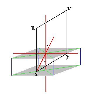
In Figure 22 we see that the projection of the face pole of the face a : b : mc does not lie on the bisector of the relevant quadrant of the projection plane, and in Figure 25 we see that the projection of the face pole of the face a : b : ~c lies on the perimeter of the projection plane and on the bisector. With a : b : ~c we have a vertical face cutting off unit distances from the clino and ortho axes. See Figure 25a. This face can be brought into an inclined position (inclined towards the vertical axis) when we turn it about X---Y (this line serving as a hinge), such that it intersects the vertical axis at m times unit distance. We then have the face a : b : mc. Where will we find the projection of the corresponding face pole of this face on the projection plane? Figure 25a can help us to explain that it will not lie on the bisector, even when that of the face a : b : ~c does.
 |
|
Figure 25a.
The vertical face a : b : ~c (xyuv) and its relation to the monoclinic axial system. When we turn this face about the hinge x--y (towards the positive direction of the vertical crystallographic axis) we get the face a : b : mc. Note that the hinge x--y is not horizontal but inclined.
|
When we turn the face a : b : ~c (xyuv) about the hinge x--y till it cuts m times unit distance from the vertical axis, then we must realize that we turn it obliquely because x--y is tilted with respect to the horizontal plane.
If that face would be turned about a horizontal hinge then stereographically we would move the projection of the corresponding face pole inwardly along the bisector, See Figure 25b.
 |
|
Figure 25b.
If the vertical face a : b : ~c (xyuv in Figure 25a) would be turned about a horizontal hinge its stereographic projection would move inwardly along the bisector.
|
But if that vertical face would (in order to generate the face a : b : mc) be turned about x--y, then it is turned about an oblique hinge and the corresponding movement of the projection of its face pole would be as indicated in the next Figure.
 |
|
Figure 25c.
If the vertical face a : b : ~c (xyuv in Figure 25a) would be turned about an oblique hinge (such as
x--y) its stereographic projection would move inwardly not along the bisector.
|
This is why the stereographic projection of the face a : b : mc does not lie on the bisector, even when the face a : b : ~c does so.
Remark : Of course the face a : b : ~c does, all by itself, not need to be precisely on the bisector of the relevant quadrant of the projection plane, because here we have to do with monoclinic crystals in which all crystallographic axes are non-equivalent. This means that the absolute cut-off distances associated with the unit face, namely one unit distance with respect to the a axis, one unit distance with respect to the b axis, and one unit distance with respect to the c axis, are not necessarily the same. In all cases where they are indeed unequal to each other this unequality will show up in the corresponding stereographic projections. But still the above described effect concerning an oblique hinge holds, causing the inclined plane to have its projected face pole shifted accordingly.
The face na : b : ~c is also vertical. It generates a monoclinic clinoprism when subjected to the symmetry elements of the present Class : The face is reflected in the mirror plane, yielding a vertical face pair. This pair is then rotated by 1800 about the 2-fold rotation axis resulting in another vertical face pair opposite to the first one. These two face pairs make up the monoclinic clinoprism. Figure 26 depicts this stereographically.
 |
|
Figure 26.
(1). Position of the face na : b : ~c in the stereogram of the symmetry elements of the Monoclinic-prismatic Crystal Class.
(2). Duplication of the face in virtue of the action of the mirror plane, resulting in a vertical face pair.
(3). Generation of an opposite vertical face pair by the action of the 2-fold rotation axis, resulting in four vertical faces making up a Monoclinic Clinoprism.
|
The face a : nb : ~c is also vertical. It generates a monoclinic orthoprism when subjected to the symmetry elements of the present Class : The face is reflected in the mirror plane, yielding a vertical face pair. This pair is then rotated by 1800 about the 2-fold rotation axis resulting in another vertical face pair opposite to the first one. These two face pairs make up the monoclinic orthoprism. Figure 27 depicts this stereographically.
 |
|
Figure 27.
(1). Position of the face a : nb : ~c in the stereogram of the symmetry elements of the Monoclinic-prismatic Crystal Class.
(2). Duplication of the face in virtue of the action of the mirror plane, resulting in a vertical face pair.
(3). Generation of an opposite vertical face pair by the action of the 2-fold rotation axis, resulting in four vertical faces making up a Monoclinic Orthoprism.
|
The face ~a : b : mc is parallel to the clino axis. It generates a monoclinic clinodome when subjected to the symmetry elements of the present Class : The face is reflected in the mirror plane, yielding an upper face pair. This pair is then rotated by 1800 about the 2-fold rotation axis resulting in a lower face pair obliquely beneath the first one. These two face pairs make up the monoclinic clinodome. Figure 28 depicts this stereographically. In the stereographic projection we see that the position of our face is just below the E-W diameter of the projection plane. This is because the clino axis is tilted by the angle beta. The extent by which the projection of the face pole of our (initial) face is moved away from the E-W diagonal corresponds exactly with that angle beta.
 |
|
Figure 28.
(1). Position of the face ~a : b : mc in the stereogram of the symmetry elements of the Monoclinic-prismatic Crystal Class.
(2). Duplication of the face in virtue of the action of the mirror plane, resulting in an upper face pair.
(3). Generation of a lower face pair by the action of the 2-fold rotation axis, resulting in four faces parallel to the clino axis making up a Monoclinic Clinodome.
A small red circle represents a lower face.
|
The face a : ~b : mc is parallel to the ortho axis. It generates a monoclinic orthohemidome when subjected to the symmetry elements of the present Class : The mirror plane does not generate any new face, but the 2-fold rotation axis generates a second face opposite to the first. The resulting Form consists of two faces parallel to the ortho axis, a monoclinic orthohemidome, in the present case a negative one. See Figure 29.
Figure 29. (1). Position of the face a : ~b : mc in the stereogram of the symmetry elements of the Monoclinic-prismatic Crystal Class.
(2). The mirror plane does not have any effect. The face is duplicated by the action of the 2-fold rotation axis resulting in two faces parallel to the ortho axis, but intersecting the vertical axis, a negative orthohemidome. Small red solid dots represent upper faces, small red (open) circles represent lower faces.
The positive orthohemidome can be generated from the face a : ~b : -mc, i.e. a same face as the one just used, but for which the derivation coefficient referring to the vertical axis is negative. See Figure 30.
Figure 30. (1). Position of the face a : ~b : -mc in the stereogram of the symmetry elements of the Monoclinic-prismatic Crystal Class.
(2). The mirror plane does not have any effect. The face is duplicated by the action of the 2-fold rotation axis resulting in two faces parallel to the ortho axis, but intersecting the vertical axis, a positive orthohemidome. Combining the negative and positive Orthohemidomes yields an Orthodome, i.e. a horizontal prism, parallel to the ortho axis.
The face ~a : b : ~ c is parallel to the clino and vertical axes. It generates a monoclinic clinopinacoid when subjected to the symmetry elements of the present Class : The face is reflected in the mirror plane resulting in a vertical face pair parallel to the clino axis, the clinopinacoid. See Figure 31.
Figure 31. (1). Position of the face ~a : b : ~ c in the stereogram of the symmetry elements of the Monoclinic-prismatic Crystal Class.
(2). Duplication of the face by the action of the mirror plane. The 2-fold rotation axis is then implied. The resulting Form consists of two vertical faces parallel to the clino axis, the Monoclinic Clinopinacoid.
The face a : ~b : ~c is parallel to the ortho and vertical axes. It generates a monoclinic orthopinacoid when subjected to the symmetry elements of the present class : The face is rotated by 1800 about the 2-fold rotation axis, resulting in a vertical face pair parallel to the ortho axis. The mirror plane is then implied. So the new Form consists of those two vertical faces parallel to the ortho axis, an orthopinacoid. See Figure 32.
Figure 32. (1). Position of the face a : ~b : ~c in the stereogram of the symmetry elements of the Monoclinic-prismatic Crystal Class.
(2). Duplication of the face by the action of the 2-fold rotation axis. The mirror plane does not generate any new faces. The resulting Form consists of two vertical faces parallel to the ortho axis, the Monoclinic Orthopinacoid.
The face ~a : ~b : c is parallel to the clino and ortho axes. It is however not horizontal, but tilted, because the clino axis is not perpendicular to the vertical axis. It generates the monoclinic basic pinacoid when subjected to the symmetry elements of the present Class : The face is rotated by 1800 about the 2-fold rotation axis resulting in a face pair parallel to the ortho and clino axes, the basic pinacoid. The tilted orientation of the faces of the basic pinacoid is expressed in the stereographic projection by the fact that the projections of those faces do not coincide with the center of the projection plane (bounded by the (dashed) circle). See Figure 33.
Figure 33. (1). Position of the face ~a : ~b : c in the stereogram of the symmetry elements of the Monoclinic-prismatic Crystal Class.
(2). Duplication of the face by the action of the 2-fold rotation axis. The mirror plane does not generate any new faces. The resulting Form consists of two faces parallel to the clino and ortho axes, the Monoclinic Basic Pinacoid.
This concludes our exposition of the Monoclinic-prismatic Crystal Class.
To continue, klick HERE for Part Two (Class 2).
back to homepage
****************